Tools Required
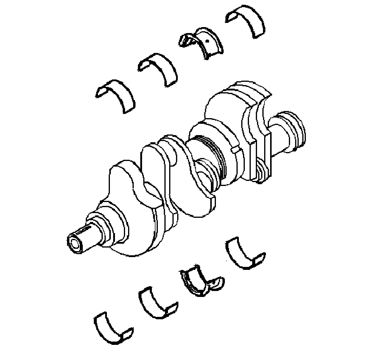
Important: Use care when handling the crankshaft. Avoid
damage to the crankshaft position sensor reluctor wheel teeth. Nicks, burrs or other
damage to the teeth may effect On-board Diagnostics (OBD II) system performance.
- Clean the crankshaft of the following elements:
- Inspect the crankshaft oil passages for obstructions.

- Inspect the crankshaft keyway for the following
conditions:
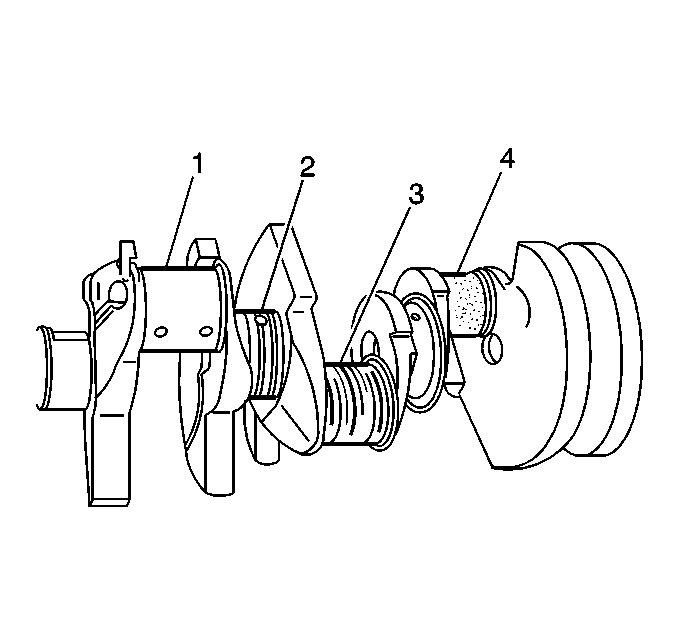
| • | A worn crankshaft key (1) |
| • | A worn crankshaft keyway (2) |
- Inspect the crankshaft threads (3) for damage.
Important: If cracks, severe gouges or burned spots
are found, replace the crankshaft. Remove slight roughness using a fine polishing
cloth soaked in clean engine oil. Remove any burrs using a fine oil stone.
- Inspect the crankshaft bearing journals and the crankshaft thrust surfaces
for the following conditions:
| • | Wear without any grooves or scratches (1) |
| • | Scratches or excessive wear (3) |
| • | Pitting or embedded bearing material (4) |
| • | Inspect the
corresponding crankshaft bearing inserts for embedded material and determine the source
of the material. |
| • | Overheating, discoloration |
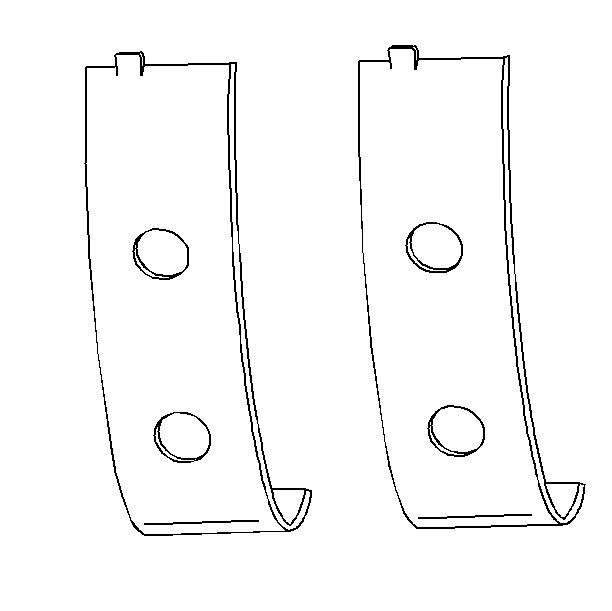
- The
crankshaft bearings are the precision insert type.
- Inspect the outer surfaces of the crankshaft bearings for the following
conditions:
| • | Wear--surface wear indicates either movement of the insert, or high
spots in the surrounding material spot wear. |
| • | Overheating or discoloration |
| • | Looseness or rotation indicated by flattened tangs and wear grooves |
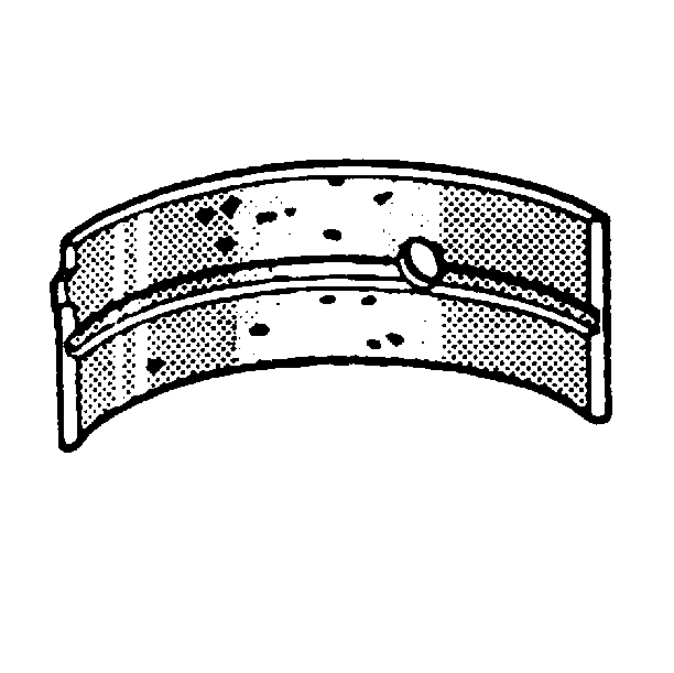
Important: Note the location of the crankshaft main
bearing high spots. If the spots are not in line, the crankshaft is bent. Replace
the crankshaft.
- Inspect the crankshaft main bearings for craters or pockets. Flattened sections
on the crankshaft bearing halves also indicate fatigue.
- Inspect the thrust surfaces of the main thrust bearing for the following
conditions:
| • | Grooving--Grooves are caused by irregularities of the crankshaft
thrust surface. |
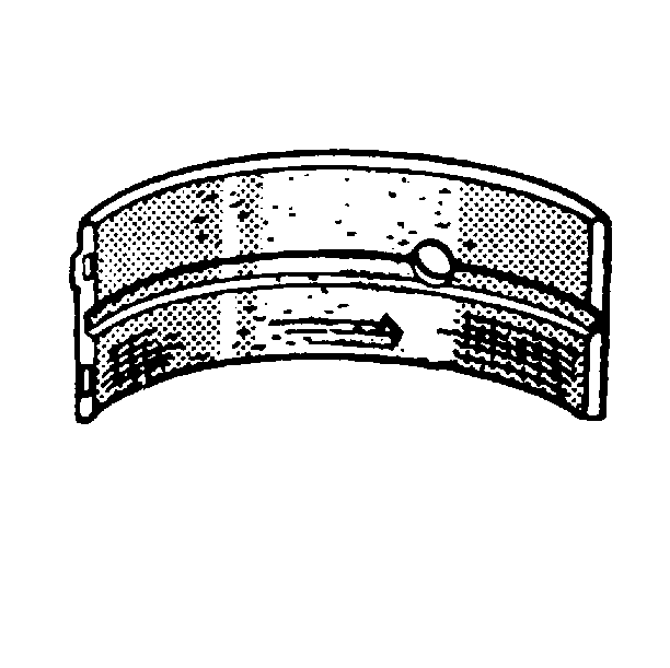
- Inspect
the crankshaft bearings for excessive scoring or discoloration.
- Inspect the crankshaft main bearings for dirt or imbedded debris.
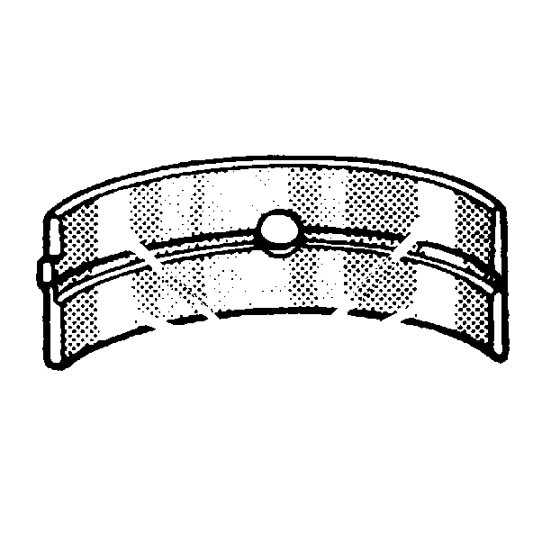
- Inspect
the crankshaft main bearings for improper seating indicated by bright, polished sections.
- Inspect the crankshaft bearings for uneven side-to-side wear. This may
indicate a bent crankshaft or a tapered bearing journal.
Important: If crankshaft bearing failure is due to conditions
other than normal wear, investigate the cause of the condition. Inspect the crankshaft
or connecting rod bearing bores.
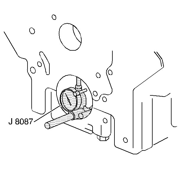
- Inspect the connecting rod bearing bores or crankshaft main bearing bores using
the following procedure:
| 14.1. | Tighten the bearing cap to specification. |
| 14.2. | Use the J 8087
in
order to measure the bearing bore for taper and out-of-round. Record the readings
for bearing selection. |
| 14.3. | No taper or out-of-round should exist. |
Bearing Selection
Measure the bearing clearance to determine the correct replacement bearing
insert size. There are two methods to measure bearing clearance. Method A gives
more reliable results and is preferred.
| • | Method A yields measurement from which the bearing clearance can be computed. |
| • | Method B yields the bearing clearance directly. Method B does not give
any indication of bearing run-out. |
Method A
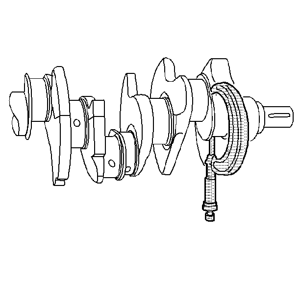
Important: Do not mix inserts of different nominal size
in the same bearing bore.
- Measure the crankshaft bearing journal diameter with a micrometer in several
places, 90 degrees apart. Average the measurements.
- Measure the crankshaft bearing journal taper and runout.
- Install the crankshaft bearing inserts. Tighten the bearing cap bolts
to specification using J 45059
.
- Measure the connecting rod inside diameter in the same direction as the
length of the rod with an inside micrometer.
- Measure the crankshaft main bearing inside diameter with an inside micrometer.
- Select a set of bearing inserts that will produce the desired clearance.
- If the specified clearances cannot be met, the crankshaft journals must
be reconditioned and undersized bearing inserts installed.
Method B
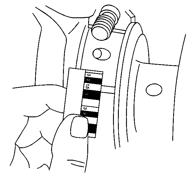
Important: Do not mix inserts of different nominal size
in the same bearing bore.
- Clean the used bearing inserts.
- Install the used bearing inserts.
- Place a piece of gaging plastic across the entire bearing width.
- Install the bearing caps.
Notice: In order to prevent the possibility of cylinder block or
crankshaft bearing cap damage, the crankshaft bearing caps are tapped into
the cylinder block cavity using a brass, lead, or a leather mallet before
the attaching bolts are installed. Do not use attaching bolts to pull the
crankshaft bearing caps into the seats. Failure to use this process may damage
a cylinder block or a bearing cap.
- Install the bearing cap bolts to specification using J 45059
.
Important: Do not rotate the crankshaft.
- Remove the bearing cap, leaving the gaging plastic in place. It does not matter
whether the gaging plastic adheres to the journal or to the bearing cap.
- Measure the gaging plastic at its widest point with the scale printed
on the gaging plastic package.
- Remove the gaging plastic.
- Select a set of bearing inserts that will produce the desired clearance.


