SERVICE REPLACEMENT TRANS. PROGRAM INTRO & ON-CAR REPAIR

MODELS AFFECTED: 1991 PARK AVENUE
BULLETIN COVERS:
The Hydra-Matic 4T60-E Service Replacement Transmission Assembly (SRTA) Program beginning May 1, 1990, and limited on-car repair guidelines. SRTA models and on-car service parts can be ordered for all 1991 Park Avenue models from your local General Motors Service Parts Operation (GMSPO) Parts Distribution Center.
The Hydra-Matic 4T60-E is a new transaxle model that has electronic shift controls to control shift points.
SRTA ADVANTAGES:
- A SRTA is the product of a highly successful, customer satisfaction driven program that parallels the existing Hydra-Matic 3T40, Hydra-Matic 4T60 and Hydra-Matic 4L60 programs.
- GMSPO Parts Distribution Centers are committed to a 48 hour maximum delivery time for all SRTA models, with no VIP charges.
GENERAL GUIDELINES:
On-Car Service or SRTA:
- Dealership overhauls for the entire transaxle will be allowed starting October 1, 1990 (providing the technician has taken the Hydra-Matic 4T60-E one-day training class number 17002.03). Until then, limited on-car repairs and SRTA replacement will be the only service options.
- Transaxle conditions considered for SRTA usage:
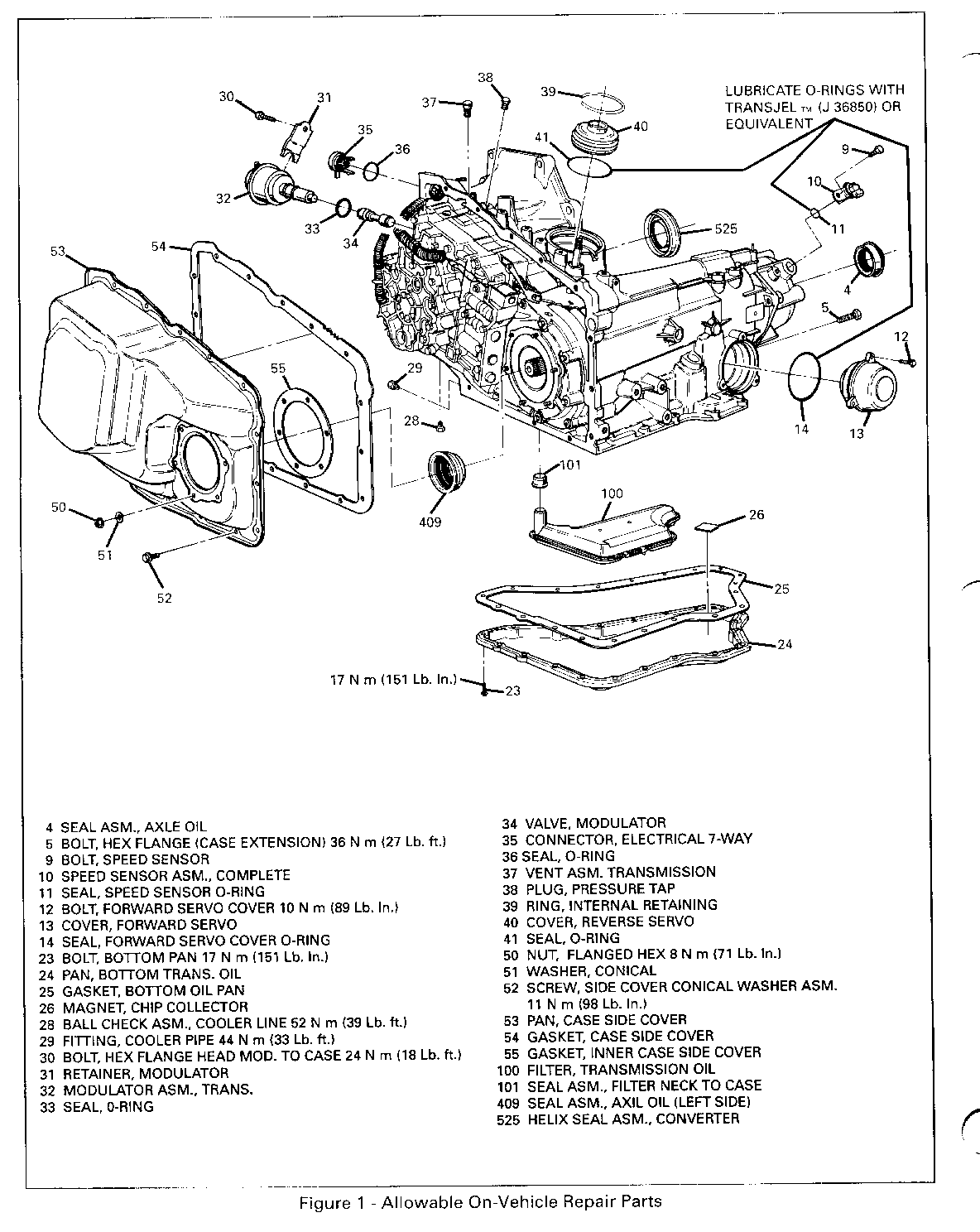
- All repairs that cannot be corrected by replacement of the parts shown in Figure 1.
- Dealer repairs on the Hydra-Matic 4T60-E transaxle include:
Limited on-vehicle serviceable items. Reference Figure 1. Parts needed to perform limited on-vehicle service on a Hydra-Matic 4T60-E transaxle are available through your local Parts Distribution Center (PDC).
IMPORTANT:
Do not attempt repairs on a Hydra-Matic 4T60-E, unless the part is shown in Figure 1 and listed in the repair part list in this bulletin. All returned Hydra-Matic 4T60-E transaxles will be disassembled and diagnosed in an effort to increase product integrity. Attempting repairs could destroy root cause analysis data.
COOLER FLUSHING:
NOTICE:
Cooler flushing MUST be performed whenever a transmission/transaxle is removed for service. It is essential to flush the cooler after SRTA installation, major overhaul, in any case of pump or torque converter replacement, or when fluid contamination is suspected. Use Kent-Moore Tool J-35944 to flush the cooler.
PARTS LIST TO COINCIDE WITH FIGURE 1
1991 HYDRA-MATIC 4T60-E SERVICEABLE COMPONENTS:
ILLUSTRATION PART NUMBER NUMBER DESCRIPTION
08666007 4 SEAL, ASM - AXLE OIL *11509041 9 BOLT (SPEED SENSOR) *10456034 10 SPEED SENSOR ASM. *11508600 12 BOLT (FORWARD SERVO COVER) *08651916 13 FORWARD SERVO COVER *08651567 14 SEAL O'RING (FWD SERVO COVER) *12337905 23 BOLT (BOTTOM PAN) *08651914 24 TRANSAXLE OIL PAN *08676250 25 TRANSAXLE OIL PAN GASKET (GASKET IS REUSABLE UNLESS DAMAGED) 08676164 28 BALL CHECK ASSEMBLY 08651654 29 COOLER PIPE FITTING *11509511 30 BOLT (MOD TO CASE) 08627650 31 RETAINER MODULATOR 08662967 32 MODULATOR 10054241 33 MODULATOR O'RING 08658375 34 MODULATOR VALVE *08651620 35 ELECTRICAL CONNECTOR *08651621 36 ELECTRICAL CONN. O'RING 08656536 39 RETAINING RING 08651915 40 REVERSE SERVO COVER 08658111 41 SEAL O'RING (REV SERVO) 08656394 50 NUT FLANGED 08656395 51 CONICAL WASHER 08656392 52 SCREW & CONICAL WASHER 08651472 53 SIDE COVER 08644902 54 & 55 SIDE COVER GASKET KIT *08651909 100 FILTER ASSEMBLY 08656613 101 SEAL ASSEMBLY FILTER 08644637 409 SEAL ASSEMBLY (LEFT SIDE AXLE) 08664812 525 SEAL ASSEMBLY (CONVERTER)
IMPORTANT:
Components noted with asterisk "*" are unique to the Hydra-Matic 4T60-E. Remaining components are common with the Hydra-Matic 4T60 (THM 440T4).
Parts are currently available from GMSPO for the part numbers:
08666007, 11509041, 11508600, 12337905, 08651654, 11509511, 08627650, 08662967, 10054241, 08658375, 08656536, 08658111, 08656394, 08656395, 08656392, 08651472, 08644902, 08656613, 08644637 and 08664812.
Part numbers 10456034, 08651916, 08651567, 08651914, 08676250, 08676164, 08651620, 08651621, 08651915 and 08651909 are expected to be available on 6-30-90. Until then normal part orders will not be accepted by GMSPO. Only verifiable emergency VIP orders will be accepted. SPO will make every effort to obtain parts. All parts will be placed on 400 control to waive VIP surcharges. However, the part will be shipped premium transportation at dealer's expense. All other order types will be canceled as incorrectly ordered while the 400 control is in place.
HYDRA-MATIC 4T60-E QUICK CHECK PROCEDURE:
1. Check fluid level and condition:
- Burned? Remember, brown color of the fluid MAY be OK. Refer to Service Manual.
- Low or overfilled? Correct as necessary.
2. Check service engine soon light, is it on? Also, check for stored codes. Use a TECH 1 to retrieve codes. An alternate method would be to connect the "A" and "B" terminals of the ALDL connector to find stored trouble codes. The ALDL connector is usually located under the driver's side of the dash. Remember, code 12 tells you that the diagnostic function of the Powertrain Control Module is functioning correctly. The PCM takes the place of the ECM on the 1991 Park Avenue.
- If there is a stored code other than code 12, refer to sections 6E and 8 of the 1991 service manual for diagnostic procedures.
3. Record any stored code(s) and repair the cause of code(s). Refer to the 1991 Service Manual for details.
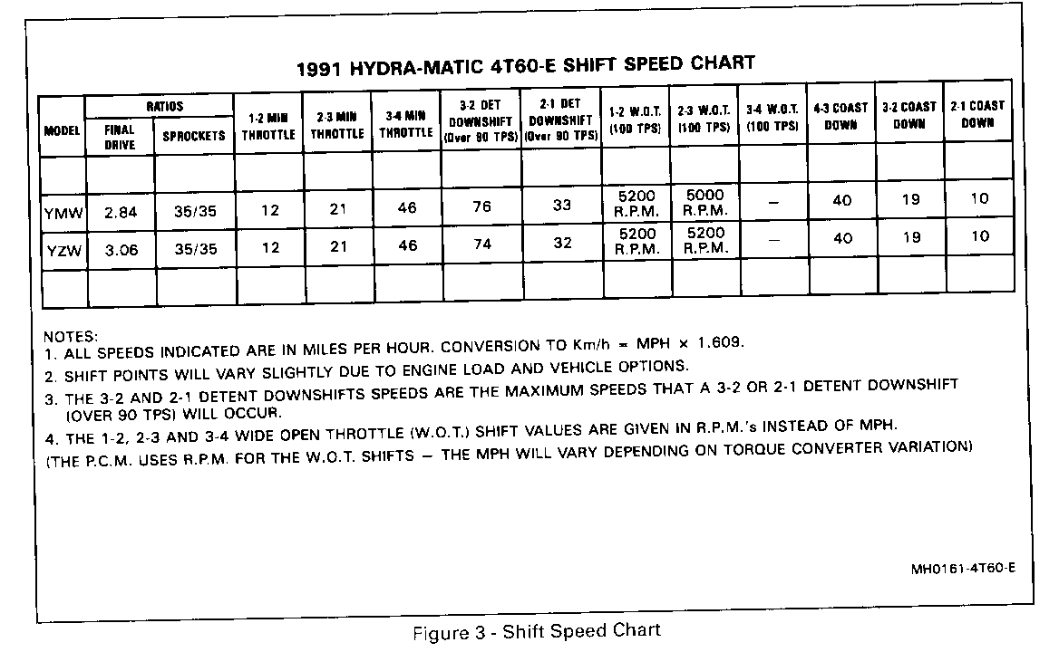
4. Clear code(s) - test drive the car. Monitor powertrain operation with a TECH 1. Refer to shift speed chart, Figure 3.
5. If transaxle operates properly - stop.
6. If transaxle does not operate properly:
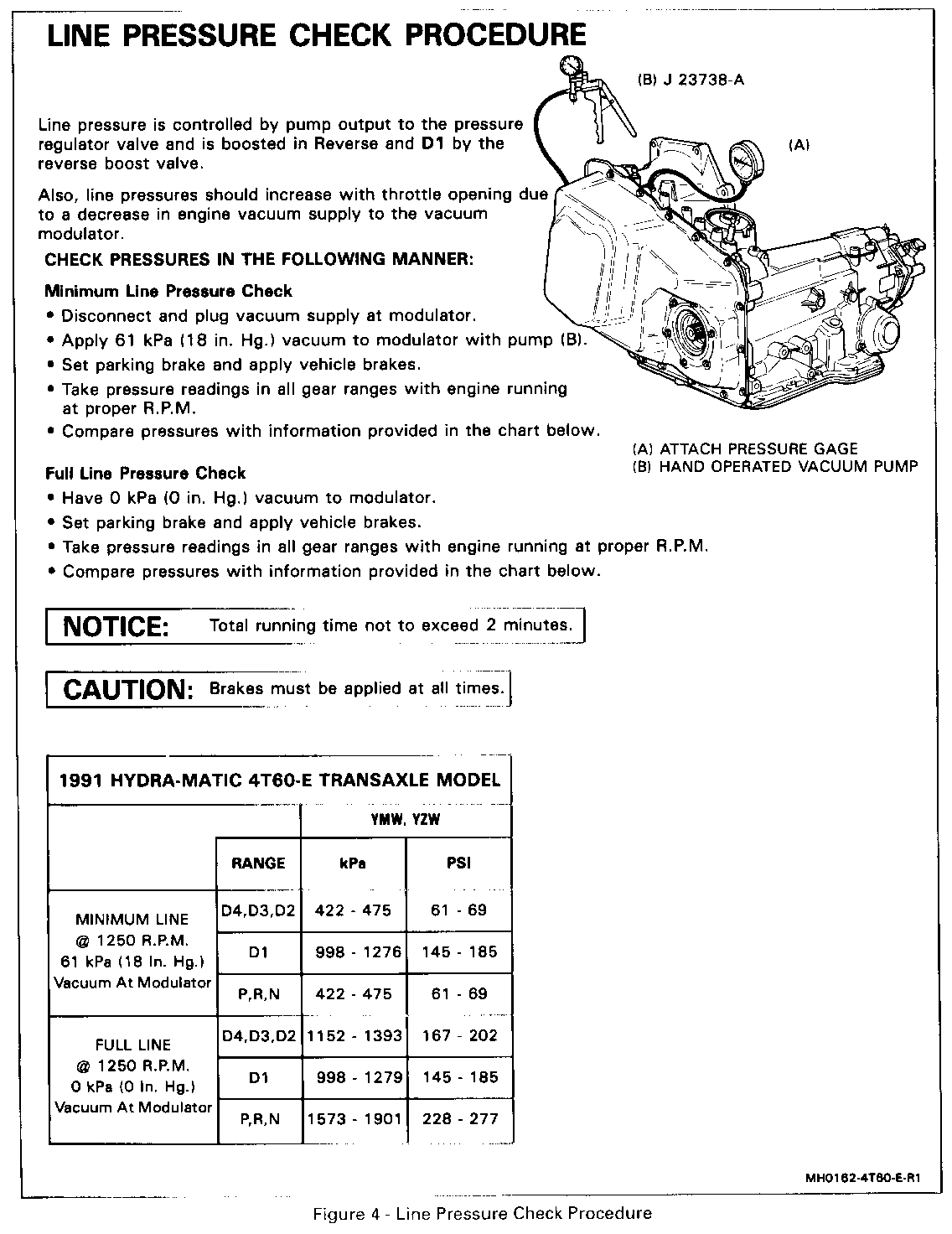
A. For harsh, soft shifts, or slippage, check the vacuum supply (refer to the chart below) and transaxle mainline pressures as shown in Figure 4. Correct as necessary.
IMPORTANT:
Altitude will affect vacuum readings as shown in the following chart:
Sea Level 48-76 kPa (Sea Level - 14-22 in. Hg.) 305 meters 45-72 kPa (1000 feet - 13-21 in. Hg.) 610 meters - 42-69 kPa (2000 feet - 12-20 in. Hg.) 914 meters - 38-66 kPa (3000 feet - 11-19 in. Hg.) 1219 meters - 34-62 kPa (4000 feet - 10-18 in. Hg.) 1524 meters - 31-58 kPa (5000 feet - 9-17 in. Hg.)
B. For an incorrect gear start (the customer complaint could be that the transaxle slips or the engine is low on power when, in fact, it is a 2nd, 3rd or 4th gear start).
B.1. Incorrect starting gear test:
The purpose of this test is to provide a method for determining when a non-first gear start is occurring.
With the engine warmed up and at a normal idle (an engine at high idle will void this test), put the gear selector in D4. On a SMOOTH LEVEL SURFACE, take your foot off the brake; does the car move forward? (Ensure the brakes are not dragging - push the car in neutral following all safety precautions).
Closely monitor the car's speed.
Move the gear selector from D4 to D2; does the car move forward at a quicker pace in D2?
- If the vehicle is quicker in D2 than in D4, the transaxle is probably not in 1st gear; most likely it is in failsafe 3rd gear.
- Putting the transaxle in D2 will hydraulically override the electronic shift controls, causing a 2nd gear start (in 2nd gear, the car will move quicker from 0 mph than in 3rd gear).
Another test would be to accelerate the car up to 55 mph and then take your foot off the throttle so that the transaxle should shift to 4th gear. Put the gear selector in D3; a shift should be felt. Then, let the car coastdown to 35 mph and put the gear selector in D2; another shift should be felt. Let the car coastdown to 20 mph and put the gear selector in D1, and another shift should be felt. All three downshifts should be felt. If not, proceed to step 8.
8. Powertrain Control Module (PCM) functional test:
The purpose of this test is to provide a method of determining proper PCM operation.
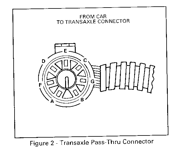
Disconnect the vehicle harness from the transaxle pass-thru connector (the wiring harness that goes from the car to the transaxle located by the vacuum modulator). Using a 12 volt test light (Kent-Moore Tool J-34142-B or equivalent), turn the ignition to the run position with the engine off and probe "E" and "F", then "E" and "G". See Figure 2, or look on the grey plastic part of the connector where the wire comes through for each wire ID.
The test light MUST light for both tests.
If not, probe terminal "E" and a good engine ground.
The test light MUST light, if not, the 15 amp ignition fuse may be blown.
If only one or both of the test(s) fail and the fuse is not blown, then the PCM, wiring, or other sensors that control the PCM may be malfunctioning or disconnected. When the PCM detects these malfunctions, it places the transaxle in the failsafe mode. Refer to the service manual sections 6E, 7 and 8 for more information.
9. Check the PRNDL switch (gear mode switch) for proper operation and adjustment. Refer to the 1991 Service Manual section 7A for details.
10. If ALL the steps check out OK and the transaxle still does not function correctly, refer to sections 6E, 7 and 8 of the 1991 Service Manual for diagnosis information. If the diagnosis information determines that an internal component of the transaxle needs to be serviced, then replace the transaxle. See page 13 of this Service Bulletin for replacement transaxle service part numbers.
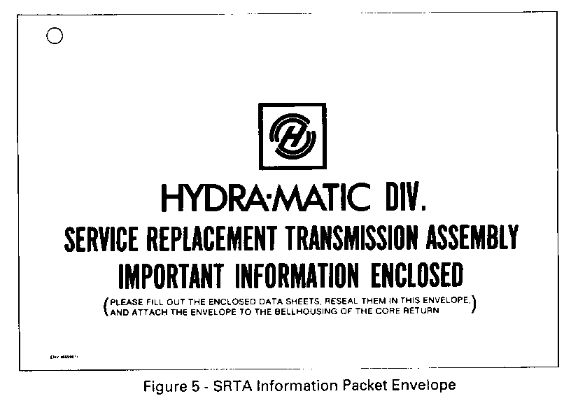
FIGURE 5
SRTA PROCESSING PROCEDURE:
Each SRTA unit will be shipped in a container which must be used for core return of the original Hydra-Matic 4T60-E assembly. A SRTA Information Packet is included with each SRTA unit. The contents of this envelope are to be removed and used as described with each illustration on the following pages.
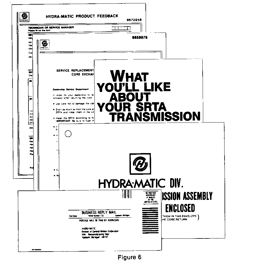
FIGURE 6
SRTA PROCESSING PROCEDURES - INFORMATION PACKET:
The contents of this packet include Limited Warranty Information, Dealer Product Feedback Form, Core Exchange Return Procedure, and a pre-addressed return mailing envelope. A dealer representative is to explain to the customer all warranty information contained in this packet.
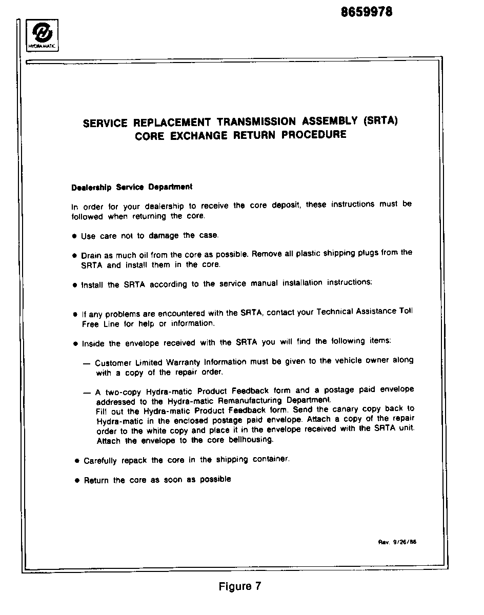
FIGURE 7
SRTA PROCESSING PROCEDURES - CORE EXCHANGE RETURN:
The core return procedure provides detailed instructions for the GM dealer on handling the SRTA and original Hydra-Matic 4T60-E units. The Hydra-Matic 4T60-E SRTA cores from May, 1990, to September, 1990, will be sent to the Hydra-Matic transaxle plant in Warren, Michigan, for analysis. Beginning October, 1990, all Hydra-Matic 4T60-E SRTA cores will be sent to the SRTA remanufacturer. The shipping labels are included in the package.
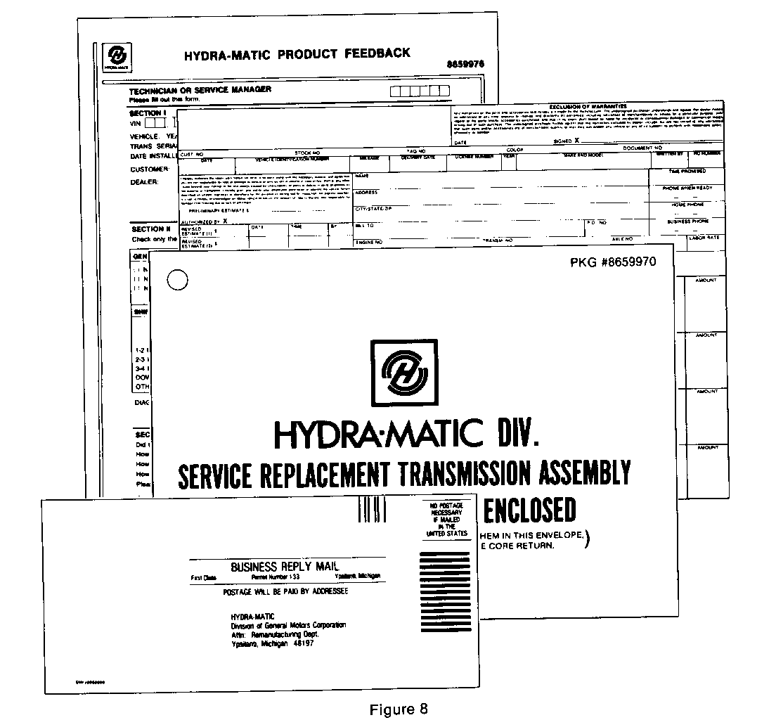
FIGURE 8
SRTA PROCESSING PROCEDURES - FAILURE ANALYSIS INFORMATION:
This Product Feedback Form is to be completed by the service manager and/or technician. Fill out this form as completely as possible to provide information which can be used for analysis. This valuable input can result in future product refinement through corrective action. Insert the white copy of the completed form and a copy of the repair order into the SRTA Information Packet envelope, reseal the envelope and wire tag it to the bell housing of the unit being returned for core exchange. Return the yellow copy of the completed Product Feedback form, using the postage paid envelope, to Hydra-Matic Division.
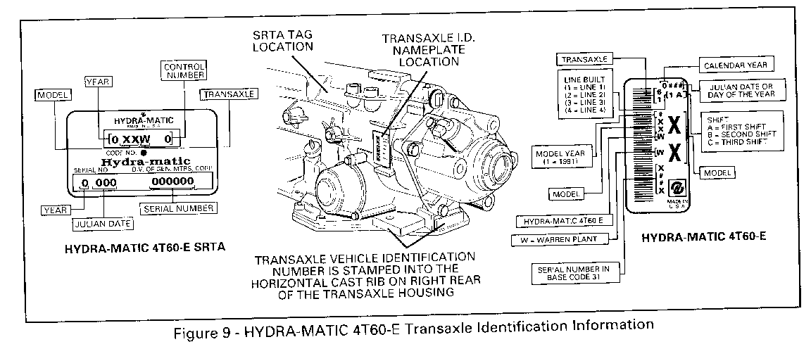
FIGURE 9
HYDRA-MATIC 4T60-E TRANSAXLE IDENTIFICATION INFORMATION:
Transaxle identification information and the SRTA model replacement chart will assist in selecting the correct SRTA unit to order from your local Parts Distribution Center.
HYDRA-MATIC 4T60-E SRTA MODEL REPLACEMENT CHART:
SRTA Part Model
8651950 YMW 8651951 YZW
PARTS INFORMATION:
Part numbers are accurate at the time of printing and subject to change. Refer to the latest GMSPO Parts Catalog for part numbers of SRTA models listed.
Parts are currently available from GMSPO for part numbers 8651950 and 8651951.
General Motors bulletins are intended for use by professional technicians, not a "do-it-yourselfer". They are written to inform those technicians of conditions that may occur on some vehicles, or to provide information that could assist in the proper service of a vehicle. Properly trained technicians have the equipment, tools, safety instructions and know-how to do a job properly and safely. If a condition is described, do not assume that the bulletin applies to your vehicle, or that your vehicle will have that condition. See a General Motors dealer servicing your brand of General Motors vehicle for information on whether your vehicle may benefit from the information.
