ELECT SERVICE MANUAL UPDATE REVISED (ABS) CHARTS

SUBJECT: ELECTRICAL SYSTEMS MANUAL UPDATE - ELECTRICAL DIAGNOSIS - ANTILOCK BRAKE SYSTEM CHARTS (REVISED)
MODELS AFFECTED: 1991 PARK AVENUE/ULTRA MODELS
The following are revised Diagnosis Charts for the 1991 Electrical Systems Manual:
REVISED CHARTS:
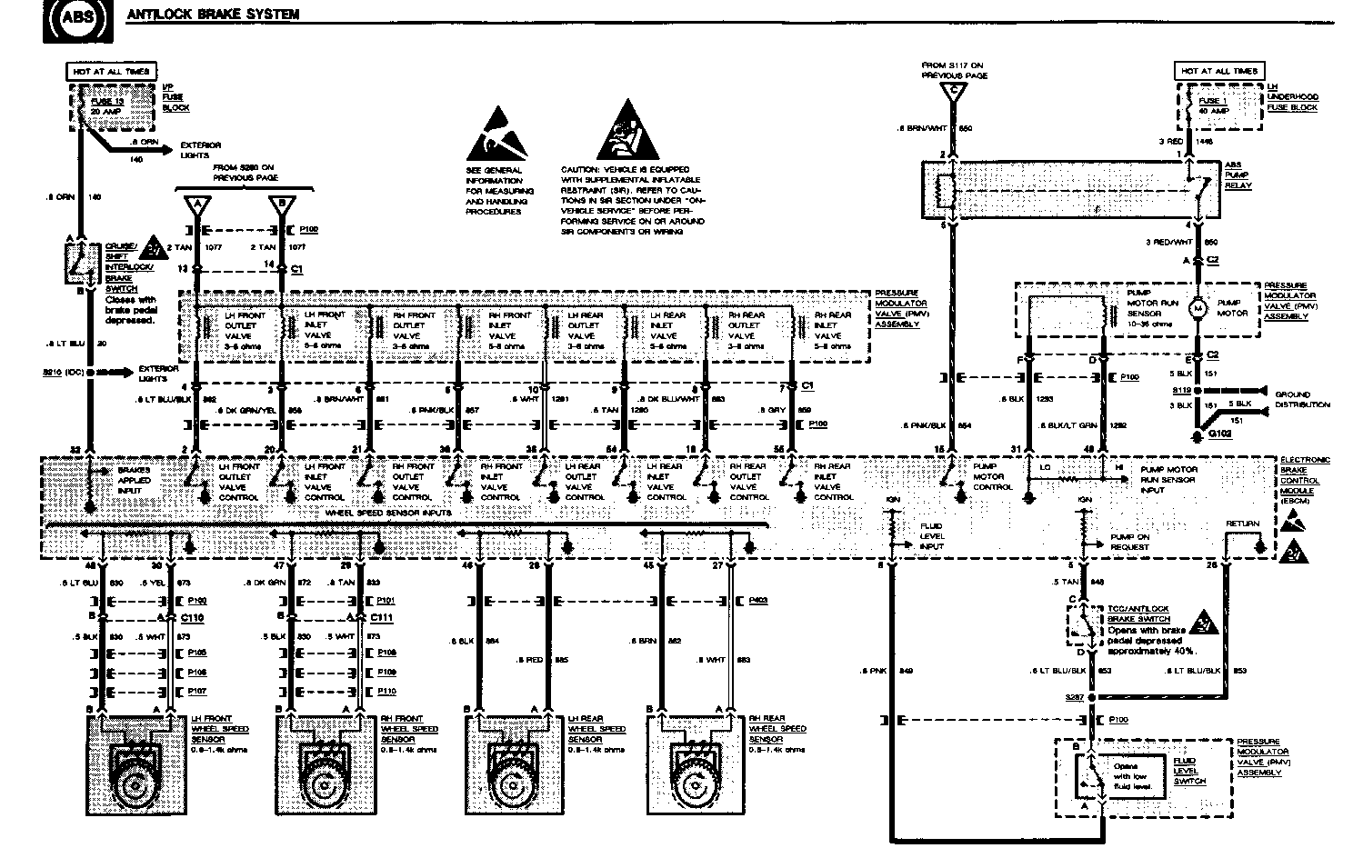
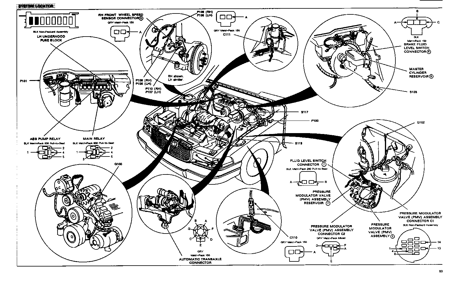
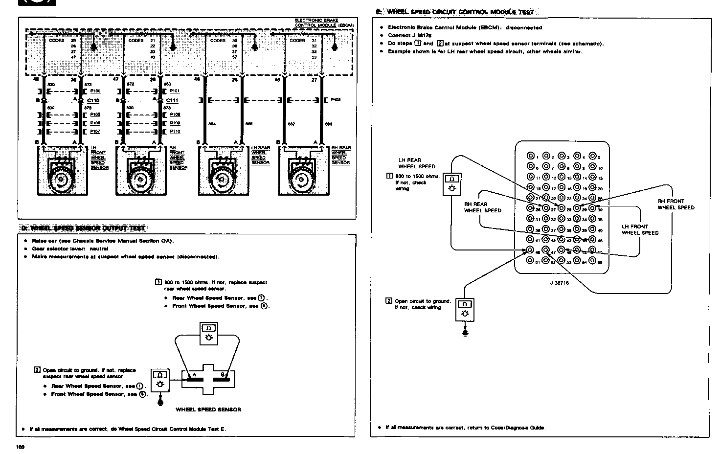
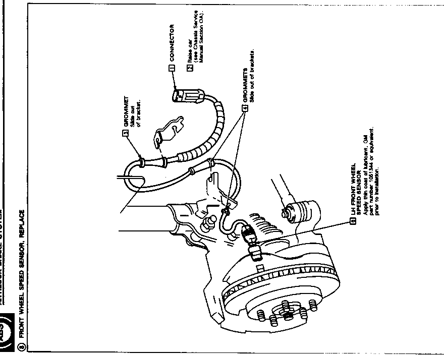
Page 92 Antilock Brake System Page 93 Antilock Brake System Page 100 Antilock Brake System Page 108 Antilock Brake System
Please update your System Manual accordingly.
FILLING AND BLEEDING PROCEDURE
o The reservoir must be properly filled to insure correct operating conditions. However, brake fluid addition is not usually necessary unless there is a leak, indicated by the BRAKE warning indicator, or the system is being serviced.
o Refer to Chassis Service Manual Section 5 for Pressure Bleeding procedure.
o Use only Delco Supreme 11 Hydraulic Brake Fluid or equivalent DOT 3 brake fluid from a clean, sealed container. Do not use DOT 5 silicone fluid.
o Thoroughly clean master cylinder reservoir cover before removal to avoid getting dirt in reservoir.
1. Fill master cylinder reservoir with brake fluid and keep at least one-half full of fluid during bleeding operation.
o Have and assistant in the vehicle to press brake pedal during bleeding operation.
o IMPORTANT: Master cylinder reservoir cap must be installed before pressing on brake pedal during bleeding operation. This will prevent the reservoir from spraying brake fluid.
o If master cylinder is known or suspected to have air in the bore, continue to step 2; otherwise go to step 9.
2. Loosen forward brake pipe connection(s) at master cylinder.
3. Allow brake fluid to flow from connector port. Maintain reservoir fluid level.
4. Tighten forward brake pipe connection(s) at master cylinder.
5. Depress brake pedal slowly one time and hold. Loosen forward brake pipe connection at master cylinder to purge air from bore. Tighten connection and then release brake pedal slowly. Wait 15 seconds. Repeat sequence, including 15 second wait, until all air is removed form bore.
6. Tighten forward brake pipe connection(s) to 15 Nm (133 lb-in).
7. After all air has been removed at forward connection(s) repeat steps 2 through 6 to bleed master cylinder at rear connection(s).
8. If it is known that calipers and wheel cylinders do not contain any air, then it is not necessary to bleed them; otherwise continue to step 9.
9. If all the wheel circuits must be bled, use the following sequence: RH rear, RH front, LH rear.
10. Remove bleeder valve cap and place proper size box-end wrench or Tool J21472 over RH bleeder valve. Attach a transparent tube over valve and allow tube to hang submerged in a transparent container, partially filled with clean brake fluid.
11. Depress brake pedal slowly one time and hold. Loosen bleeder valve to purge air from caliper/cylinder. Tighten bleeder screw and slowly release pedal. Wait 15 seconds. Repeat sequence, including 15 second wait until all air is removed. It may be necessary to repeat sequence 10 or more times to remove all air. Rapid pedal pumping pushes master cylinder secondary piston down the bore in a manner that makes it difficult to bleed system.
12. Tighten wheel cylinder bleeder valves to 7 Nm (62 lb-in).
13. Fill master cylinder to proper level.
14. Check brake pedal for "sponginess"
o Repeat entire bleeding procedure to correct "sponginess".
SERVICE PARTS CATALOG COMPONENT REFERENCE NAME GROUP ---------------------------------- ---------------------------------- ABS PUMP RELAY RELAY, ELEK BRK CONT 4.720 ANTILOCK INDICATOR GAGES CLUSTER BULB (161)
INDICATORS CLUSTER BULB (174) BRACKET BRACKET, BRK PRESS MAD VLV 4.730 PRESSURE MODULATOR VALVE (PMV) ASSMY. VALVE, BRK PRESS MOD 4.730
PRESSURE MODULATOR VALVE (PMV) ASSMY. RESERVOIR, BRK PRESS MOD RESERVOIR VLV 4.730 BRAKE INDICATOR GAGES CLUSTER BULB (161)
INDICATORS CLUSTER BULB (161) CRUISE/SHIFT INTERLOCK/BRAKE SWITCH SWITCH,S/LP &A/TRNS SHFT LK & C/CONT REL 2.447 ELECTRONIC BRAKE CONTROL MODULE MODULE, ELEK BRK CONT 4.720 (ECBM)
FRONT WHEEL SPEED SENSOR SENSOR, FRT WHL SPD 4.710 IGNITION SWITCH See Chassis Service Manual Sec 3F MAIN RELAY RELAY, ELEK BRK CONT 4.720
MASTER CYLINDER RESERVOIR RESERVOIR, W/SENSOR 4.651 PARK BRAKE SWITCH SWITCH, PARK BRK WARN LP 4.589 REAR WHEEL SPEED SENSOR SENSOR, RR WHL SPD 4.710
TCC/ANTILOCK BRAKE SWITCH SWITCH, ELEK BRK CONT BRK PED & C/CONT VAC REL VLV & TCC 4.710


General Motors bulletins are intended for use by professional technicians, not a "do-it-yourselfer". They are written to inform those technicians of conditions that may occur on some vehicles, or to provide information that could assist in the proper service of a vehicle. Properly trained technicians have the equipment, tools, safety instructions and know-how to do a job properly and safely. If a condition is described, do not assume that the bulletin applies to your vehicle, or that your vehicle will have that condition. See a General Motors dealer servicing your brand of General Motors vehicle for information on whether your vehicle may benefit from the information.
