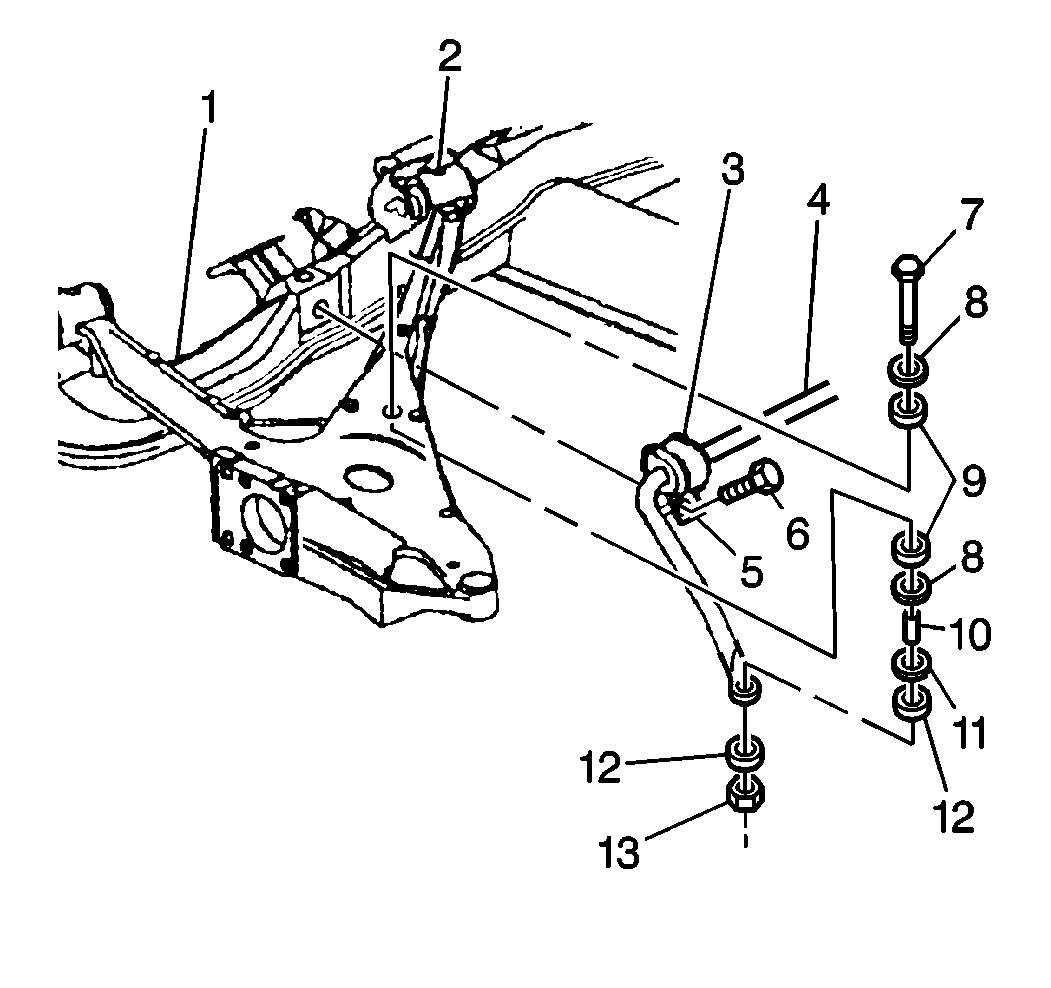
Removal Procedure
- Raise and support the vehicle. Refer to
Vehicle Lifting Caution
in General Information.
- Remove the tire and wheel assemblies. Refer to
Wheel Removal
in Wheels and Tires.

- Remove the ELC height
sensor link from the control arm (2).
- Remove the two bolts. Move the ELC height sensor for clearance
when removing the stabilizer shaft (4).
- Remove the following from the control arm (2):
| • | The stabilizer shaft link assembly bolt (7) |
- Remover the clamp bolt (6). Bend the open end of the clamp (5)
upward.
- Remove the stabilizer shaft (4) and the insulator (3).
Installation Procedure

- Install the stabilizer
shaft (4) and the insulator (3).
- Install the insulator (3) into the clamp (5) with the slit forward.
- Bend the link downward to close around the insulator. Center the
stabilizer shaft (4).
- Install the clamp bolt (6).
- Install the link assembly insulators (9, 12), the sleeve (10),
and the retainers (8, 11).
- Install the support bolt
(7) and the nut (13).
Tighten
| • | Tighten the link assembly bolt (7) to 13 N·m (115 lb in). |
| • | Tighten the clamp bolt (6) to 33 N·m (24 lb ft). |
- Install the ELC height sensor.
- Install the two bolts.
Tighten
Tighten the bolts to 7 N·m (62 lb in).
- Install the height sensor link to the control arm (2).
- Install the tire and the wheel assemblies. Refer to
Wheel Installation
.
- Lower the vehicle.


