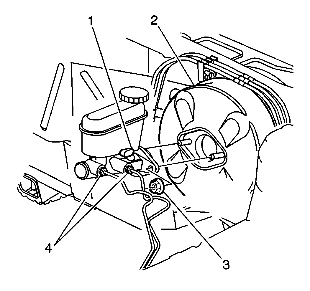
For 1990-2009 cars only
Removal Procedure
- Disconnect the retainer and electrical connector from the fluid level sensor.
- Drain the brake fluid from the master cylinder reservoir.
- Disconnect the reservoir hose from the master cylinder.
- Plug the hose to prevent a fluid loss or contamination.
- Disconnect the brake pipes from the master cylinder.
- Plug the open pipes to prevent a fluid loss or contamination.
- Remove the two attaching nuts.
- Remove the master cylinder.
- Remove the reservoir if it is to be used on the replacement master cylinder.

Installation Procedure
- Connect the reservoir onto the master cylinder as needed. Refer to Master Cylinder Cover/Caps Replacement .
- Install the master cylinder onto the power booster.
- Install the attaching nuts.
- Install the brake pipes.
- Connect the reservoir hose onto the master cylinder.
- Fill the master cylinder reservoir to the full level mark using only Delco® Supreme II Brake Fluid or the equivalent, DOT 3 brake fluid, as specified in Maintenance and Lubrication.
- Connect the electrical connector to fluid level sensor, secure with retainer.
- Bleed the hydraulic system. Refer to Hydraulic Brake System Bleeding .
- Recheck the fluid level in the reservoir.

Bench bleed the master cylinder prior to the installation to remove any trapped air. Perform this procedure on a level surface. Use a tool that will not score the bore of the master cylinder. Apply pressure to the plunger as many times as needed to circulate the brake fluid completely through the master cylinder. Allow the brake fluid and trapped air to be released through the inlet and outlet ports on the master cylinder.
Tighten
Tighten to 27 N·m (20 lb ft).
Tighten
Tighten the brake pipe fittings to 15 N·m (11 lb ft).
