Tools Required
| • | J 26958 Output
Shaft Loading and Aligning tool |
| • | J 28585 Snap
Ring Remover and Installer |
| • | J 38385 Output
Shaft Loading Tool Adapter |

- If the final drive assembly
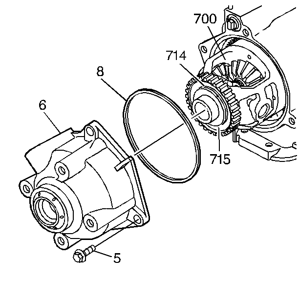
(700) has been removed it must be reinstalled.
- Make sure that the thrust washer (714) and the bearing (715) are
still on the front differential carrier.
- Install the case extension seal (8) onto the case extension (6).
- Install the case extension assembly (6) onto the transmission
case (3).
- Install only two of the four case extension bolts (5).
Tighten
Do not torque the bolts. Tighten them only until the case extension
is fully seated.

- Position the transmission
so that the case extension is facing upward.
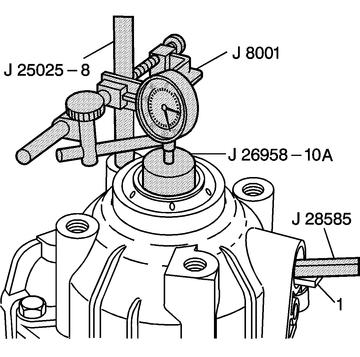
- Install J 25025-1
, J 26958-10A
, and J 8001
.
- Set the dial indicator to zero.
Important: Protect the VSS sensor bore with a piece of wood or rubber while prying
with J 28585
or a large
screwdriver.
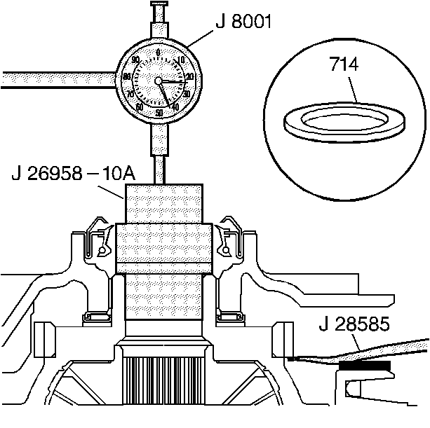
- Use J 28585
or a large
screwdriver in order to lift the front differential carrier. Pry up on the
vehicle speed sensor reluctor wheel through the sensor hole in the case extension.

- Note the dial indicator reading before changing the carrier thrust washer
(714).
| • | If the dial indicator reading is less than 0.12 mm (0.005 in),
install the next smaller size thrust washer, then recheck. |
| • | If the dial indicator reading is greater than 0.62 mm (0.025 in),
install the next larger size thrust washer, then recheck. |
| • | If the dial indicator reading is 0.12-0.62 mm (0.005-0.025 in),
the thrust washer is correct. |
- Refer to the Thrust Washer Selection Guide in
End Play Specifications
.
- Remove J 8001
and J 25025-7A
.


