CAM SENSOR TIMING DIAG. AND INSPECTION PROCEDURE

SUBJECT: CAM SENSOR TIMING
MODELS AFFECTED: 1984 3.8L TURBOCHARGED ENGINE (VIN CODE 9)
The camshaft sensor timing is important for proper fuel delivery. Should an engine performance or driveability condition be encountered and no trouble codes are stored in the ECM. The following inspections and checks should be performed:
o Spark plugs (cracked)
o Wiring and vacuum hose routing and connections
o Fuel injectors for proper flow, (See injector balance test in Chassis Service Manual).
o Possible turbo overboost condition due to PROM calibration, see Service bulletin 84-6E-27 for correction.
o Cam Sensor Installation (180 degree Out of Time)
o Cam Sensor timing, (See procedure in this bulletin)
PROCEDURE FOR CHECKING OF CAM SENSOR INSTALLATION TO ENSURE IT IS NOT TIMED 180 DEGREE OUT.
1. Remove #1 spark plug.
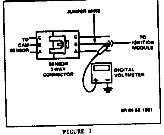
2. Using weatherpac removal tool J-28742-A, wire terminal "B" from the 3-way connector from cam sensor to coil, on the coil module side, (Figure 3).
3. Install jumper wire into terminal "B" of the 3-way connector and reconnect 3-way connectors.
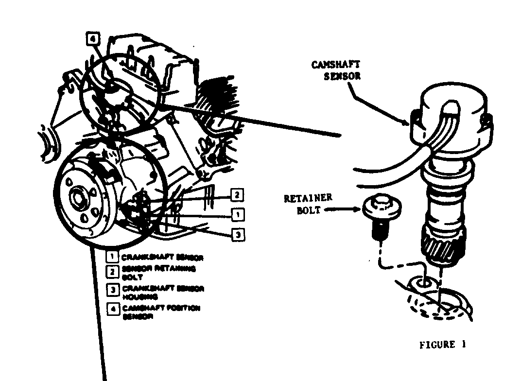
4. Connect digital volt-ohm meter between the jumper wire to ground (See Figure 1) set volt-ohm meter to 20 volt value.
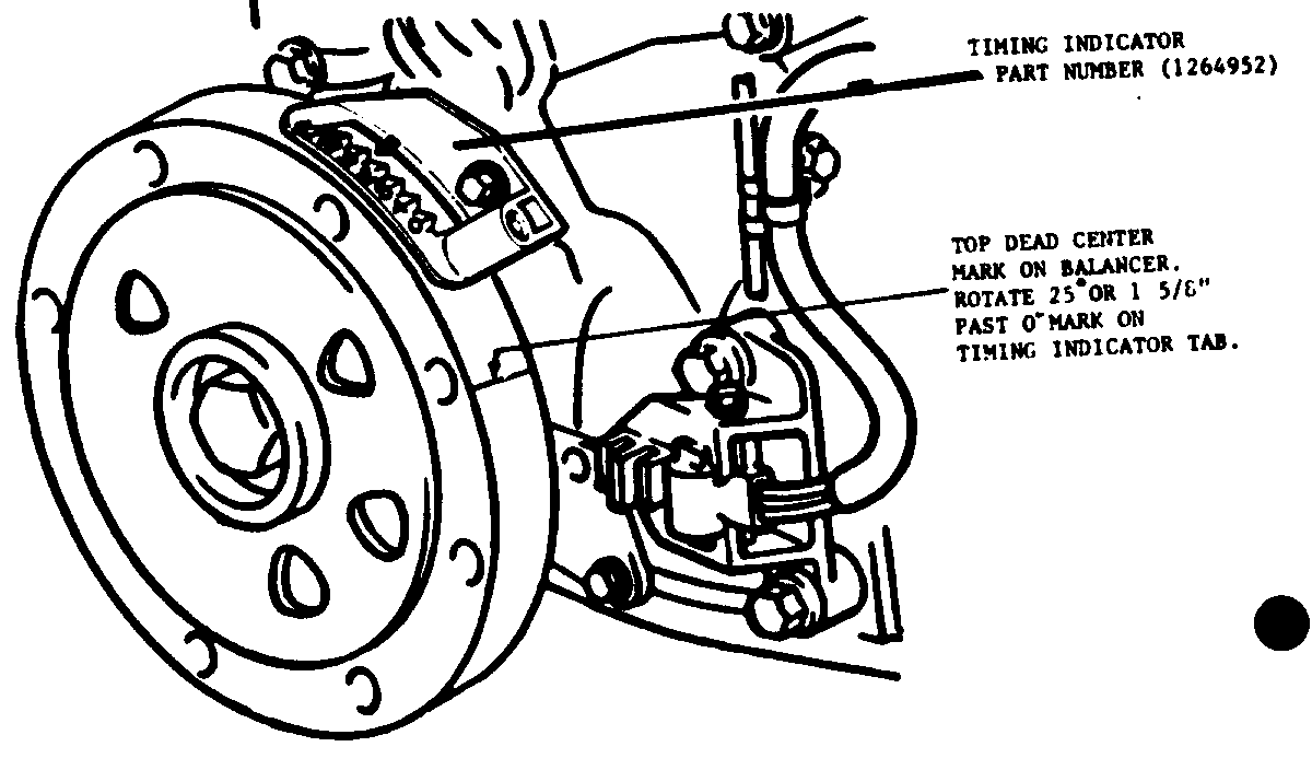
NOTICE: Same early 1984 engines may have been produced without the timing indicator tab installed on the front timing cover. On these engines timing indicator tab part number 1264952 must be ordered from WDDGM and installed (Figure 2).
5. Ignition on, engine stopped.
6. Facing the front of the engine, manually rotate crankshaft clockwise to get #1 cylinder on TDC compression stroke. With timing marks lined up monitor volt-ohm meter, slowly continue to rotate the crankshaft until the reading on the volt-meter goes from a high of (5 to 7) volts to a lower voltage. The TDC mark on the crankshaft should be at 25 degree past TDC when voltage drops (Figure 2). If voltage drops before or after the 25 degree mark past TDC position the sensor must be retimed. If the voltage does not drop until the crankshaft is rotated on around another 360 degree(1 revolution) the cam sensor is 180 degree out of time. (If removal of sensor is required follow R&R camshaft sensor procedure in this bulletin). (If voltage drops before or shortly after the crankshaft balancer mark is at 25 degree Past TDC #1 cylinder on compression stroke follow camshaft timing procedure in this bulletin).
INSTALLATION OF CAMSHAFT SENSOR
NOTICE: Proper positioning of cam sensor into the engine is critical due to wire length on cam sensor to coil pack assembly.
If it is determined that the can sensor is 180 degree out of time. Remove spark plug wires from coil assembly, electrical connector, coil pack assembly and bracket from engine to gain access to cam sensor.
Remove (2) screws retaining hall effect switch and cover assembly from cam sensor. NOTICE: Care must be used to prevent bending of cam sensor cup.
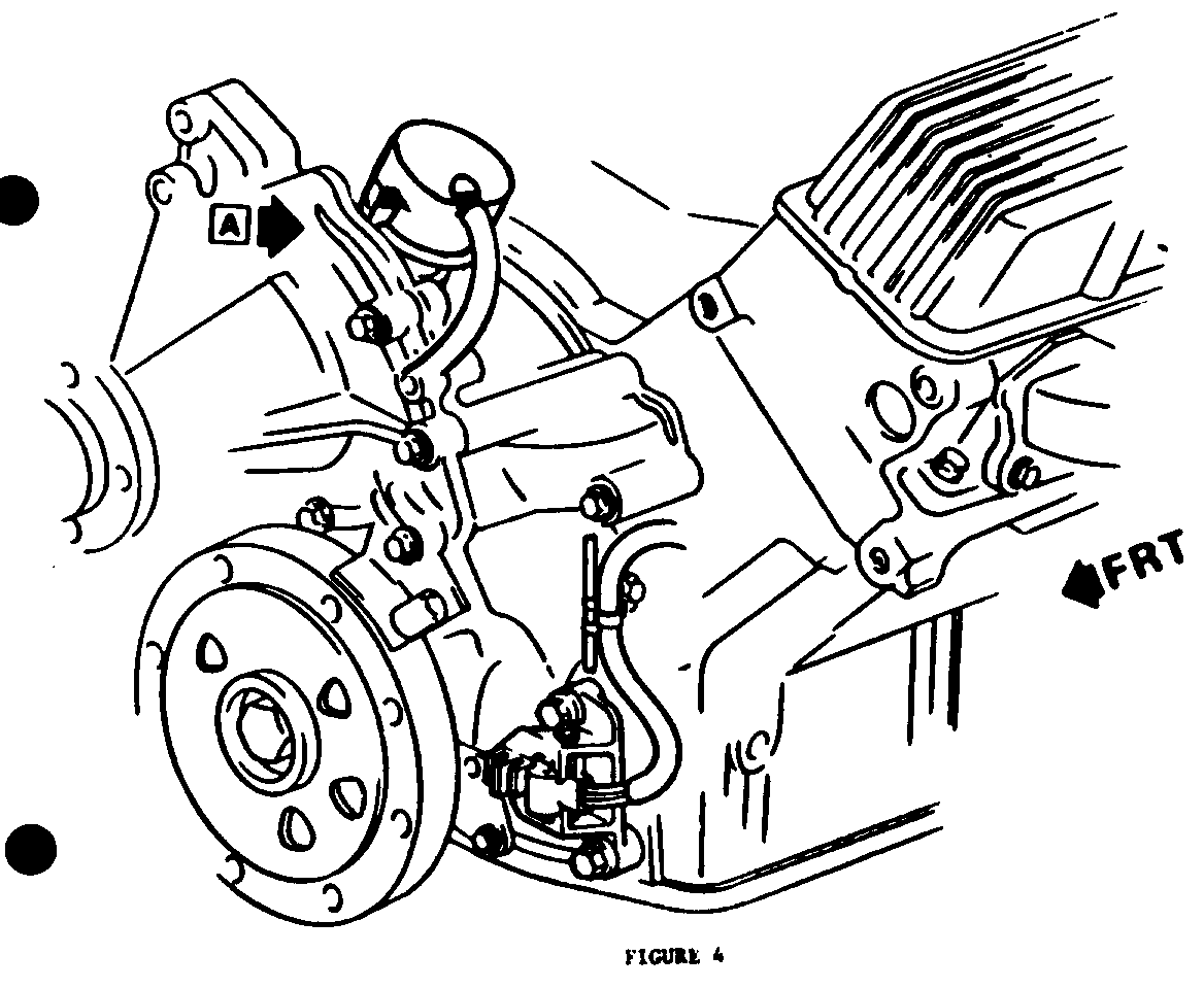
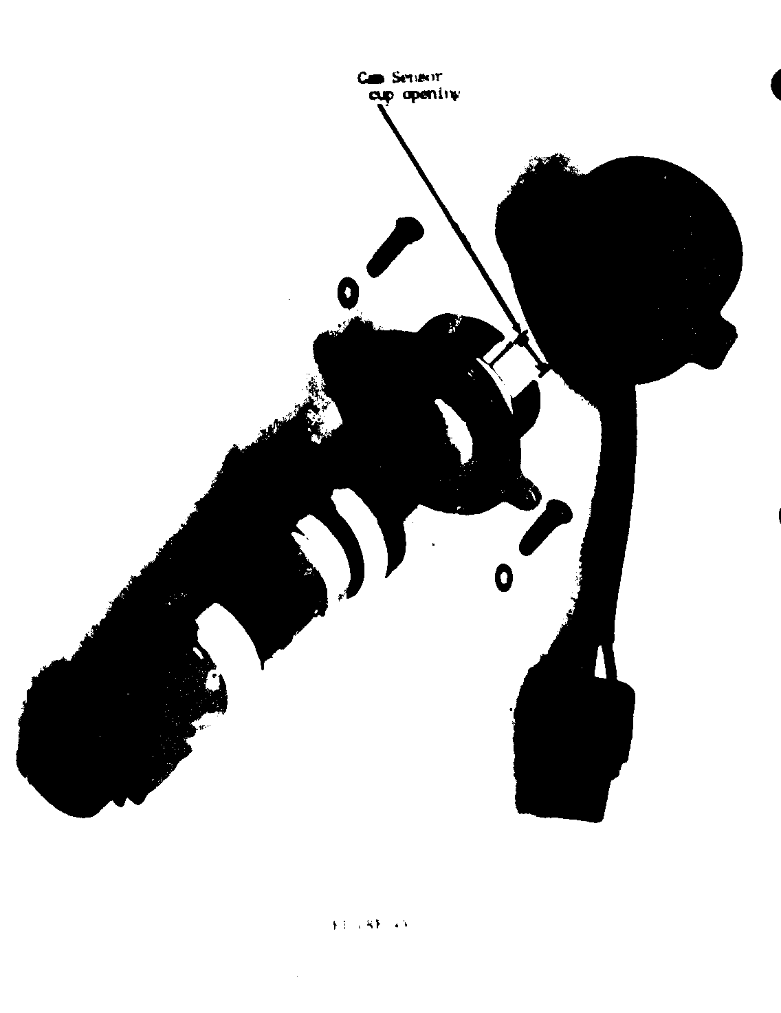
Remove #1 spark plug if not already removed, turn engine over by hand until #1 cylinder is on top dead center compression stroke. Note position of window (opening) in cam sensor cup. (Sensor cup opening should be pointing at the power steering pump assembly, figure 4 & 4A).
Remove cam sensor retainer lock down bolt and washer. Pull cam sensor up until it disengages from oil pump shaft and timing gear, rotate cup window 180 degree, reinstall sensor into position. Reinstall retainer bolt and washer assembly, leave loose for final positioning of cam sensor for exact timing.
Refer to cam sensor timing procedure for timing of cam sensor.
CAMSHAFT SENSOR TIMING PROCEDURE
1. With the timing marks lined up (compression stroke #1 cylinder) rotate the crankshaft so the timing mark is 25 degree past top dead center (See figure 2).
2. Connect a digital volt-ohm meter between the jumper wire to ground (See Figure 1) set volt ohm meter to 20 volt scale.
3. Ignition on engine stopped.
4. Loosen camshaft sensor retainer bolt, rotate camshaft sensor counter clockwise until the sensor switch just closes. This will be indicated when the voltmeter reading goes from a high of (5 to 7) volts to a lower voltage. This voltage drop indicates that the switch is closed. The camshaft sensor at this point should be rotated very slowly back clockwise until voltage on the volt ohm meter goes back to its high reading noted previously. This step insures the camshaft sensor is perfectly positioned in the edge of the on/off window.
5. Tighten camshaft sensor retaining bolt, (Figure 1).
6. Reinstall #1 plug and spark plug wires to coil.
7. Remove jumper wire and reinstall wiring harness wire into 3-way connector terminal "B" (Figure 3).
General Motors bulletins are intended for use by professional technicians, not a "do-it-yourselfer". They are written to inform those technicians of conditions that may occur on some vehicles, or to provide information that could assist in the proper service of a vehicle. Properly trained technicians have the equipment, tools, safety instructions and know-how to do a job properly and safely. If a condition is described, do not assume that the bulletin applies to your vehicle, or that your vehicle will have that condition. See a General Motors dealer servicing your brand of General Motors vehicle for information on whether your vehicle may benefit from the information.
