Camshaft Timing Chain and Sprocket Replacement L36 (VIN K)
Removal Procedure
- Remove the engine front cover. Refer to Engine Front Cover Replacement .
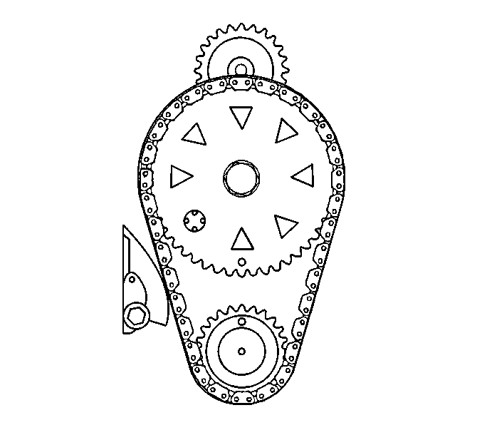
- Align the timing marks on the sprockets so that they are as close as possible.
- Remove the timing chain dampener.
- Remove the camshaft sprocket bolt.
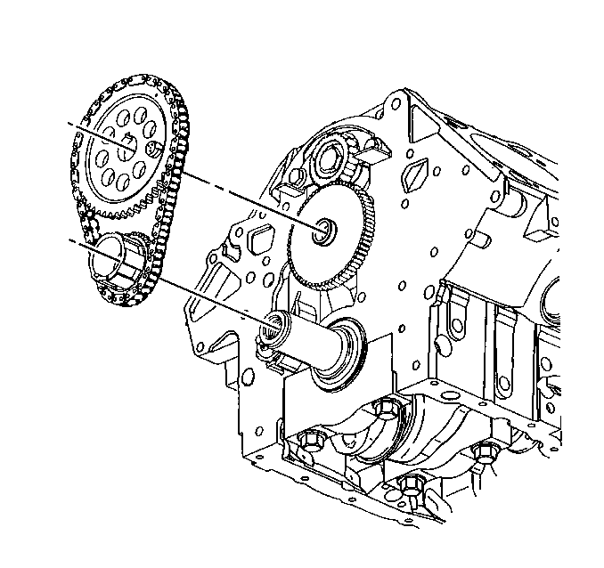
- Remove the camshaft sprocket and the timing chain.
- Remove the crankshaft sprocket.
- Remove the balance shaft drive gear in order to access the camshaft thrust plate.
- Remove the camshaft thrust plate bolts.
- Remove the camshaft thrust plate.
- Remove the balance shaft driven gear bolt.
- Remove the balance shaft driven gear.
- Clean and inspect all of the components for wear and/or damage. Refer to Camshaft Timing Chain and Sprocket Cleaning and Inspection .
- If the pistons have been moved in the engine, use the following procedure:


Important: If the sprocket does not come off easily, a light blow on the lower edge of the sprocket with a plastic mallet should dislodge the sprocket.


| 13.1. | Turn the crankshaft so that the number one piston is at top dead center. |
| 13.2. | Turn the camshaft so that, with the sprocket temporarily installed, the timing mark is straight down. |
Installation Procedure
Tools Required
J 36660-A Electronic Torque Angle Meter
- Install the balance shaft driven gear.
- Prevent the balance shaft from rotating and install the balance shaft driven gear bolt.
- Install the camshaft thrust plate.
- Install the camshaft thrust plate bolts.
- Install the balance shaft drive gear.
- Align the timing marks on the balance shaft drive gear and the balance shaft driven gear.
- Install the crankshaft sprocket.
- Install the timing chain and sprocket.
- Assemble the timing chain on the sprockets with the timing marks as close together as possible.
- Install the camshaft sprocket bolt.
- Install the timing chain dampener.
- Install the engine front cover. Refer to Engine Front Cover Replacement .

Notice: Use the correct fastener in the correct location. Replacement fasteners must be the correct part number for that application. Fasteners requiring replacement or fasteners requiring the use of thread locking compound or sealant are identified in the service procedure. Do not use paints, lubricants, or corrosion inhibitors on fasteners or fastener joint surfaces unless specified. These coatings affect fastener torque and joint clamping force and may damage the fastener. Use the correct tightening sequence and specifications when installing fasteners in order to avoid damage to parts and systems.
Notice: This bolt is designed to permanently stretch when tightened, and therefore MUST be replaced anytime it is removed. The correct part number fastener must be used to replace this type of fastener. Do not use a bolt that is stronger in this application. If the correct bolt is not used, the parts will not be tightened correctly. The system or the components may be damaged.
Tighten
Tighten the balance shaft driven gear bolt to 22 N·m (16 lb ft).
Use the J 36660-A
in order
to rotate the bolts an additional 70 degrees.

Tighten
Tighten the camshaft thrust plate bolts to 15 N·m (11 lb ft).


Tighten
Tighten the camshaft sprocket bolt to 100 N·m (74 lb ft).
Use the J 36660-A
in order
to rotate the bolts an additional 90 degrees.

Tighten
Tighten the dampener bolt to 22 N·m (16 lb ft).
Important: Rotate the engine two revolutions and check the timing marks. Make sure that the marks are aligned.
Camshaft Timing Chain and Sprocket Replacement L67 (VIN 1)
Removal Procedure
- Remove the engine front cover. Refer to Engine Front Cover Replacement .
- Align the timing marks on the sprockets so that they are as close as possible.
- Remove the timing chain dampener.
- Remove the camshaft sprocket bolt.
- Remove the camshaft sprocket and the timing chain.
- Remove the crankshaft sprocket.
- Remove the balance shaft drive gear in order to access the camshaft thrust plate.
- Remove the camshaft thrust plate bolts.
- Remove the camshaft thrust plate.
- Remove the balance shaft driven gear bolt.
- Remove the balance shaft driven gear.
- Clean and inspect all of the components for wear and/or damage. Refer to Camshaft Timing Chain and Sprocket Cleaning and Inspection .
- If the pistons have been moved in the engine, use the following procedure:


Important: If the sprocket does not come off easily, a light blow on the lower edge of the sprocket with a plastic mallet should dislodge the sprocket.


| 13.1. | Turn the crankshaft so that the number one piston is at top dead center. |
| 13.2. | Turn the camshaft so that, with the sprocket temporarily installed, the timing mark is straight down. |
Installation Procedure
Tools Required
J 36660-A Electronic Torque Angle Meter
- Install the balance shaft driven gear.
- Prevent the balance shaft from rotating and install the balance shaft driven gear bolt.
- Install the camshaft thrust plate.
- Install the camshaft thrust plate bolts.
- Install the balance shaft drive gear.
- Align the timing marks on the balance shaft drive gear and the balance shaft driven gear.
- Install the crankshaft sprocket.
- Install the timing chain and sprocket.
- Assemble the timing chain on the sprockets with the timing marks as close together as possible.
- Install the camshaft sprocket bolt.
- Install the timing chain dampener.
- Install the engine front cover. Refer to Engine Front Cover Replacement .

Notice: Use the correct fastener in the correct location. Replacement fasteners must be the correct part number for that application. Fasteners requiring replacement or fasteners requiring the use of thread locking compound or sealant are identified in the service procedure. Do not use paints, lubricants, or corrosion inhibitors on fasteners or fastener joint surfaces unless specified. These coatings affect fastener torque and joint clamping force and may damage the fastener. Use the correct tightening sequence and specifications when installing fasteners in order to avoid damage to parts and systems.
Notice: This bolt is designed to permanently stretch when tightened, and therefore MUST be replaced anytime it is removed. The correct part number fastener must be used to replace this type of fastener. Do not use a bolt that is stronger in this application. If the correct bolt is not used, the parts will not be tightened correctly. The system or the components may be damaged.
Tighten
Tighten the balance shaft driven gear bolt to 22 N·m (16 lb ft).
Use the J 36660-A
in order
to rotate the bolts an additional 70 degrees.

Tighten
Tighten the camshaft thrust plate bolts to 15 N·m (11 lb ft).


Tighten
Tighten the camshaft sprocket bolt to 100 N·m (74 lb ft).
Use the J 36660-A
in order
to rotate the bolts an additional 90 degrees.

Tighten
Tighten the timing chain dampener bolt to 22 N·m (16 lb ft).
Important: Rotate the engine two revolutions and check the timing marks. Make sure that the marks are aligned.
