For 1990-2009 cars only
Removal Procedure
- Remove the throttle body air inlet duct. Refer to Throttle Body Assembly Replacement in Engine Controls.
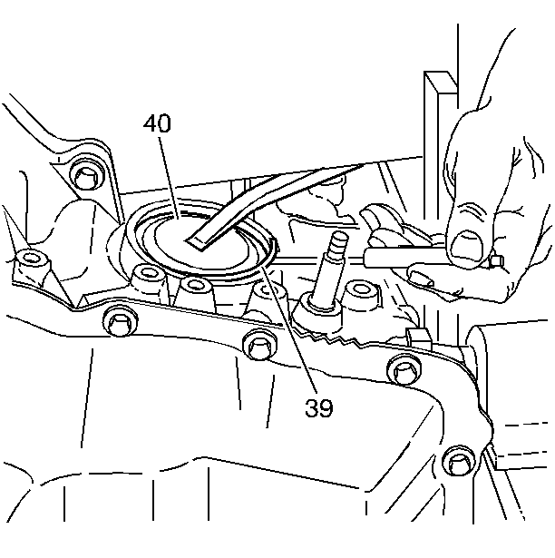
- Depress the reverse servo cover (40).
- Remove the snap ring (39).
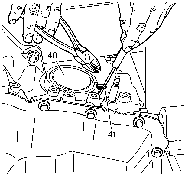
- Pull the O-ring seal (41) out through the slot in the case.
- Use side cutting pliers in order to cut the servo cover O-ring seal (41).
- Depress the reverse servo cover (40), grasp one end of the cut seal (41) and pull the seal (41) out of the servo cover (40).
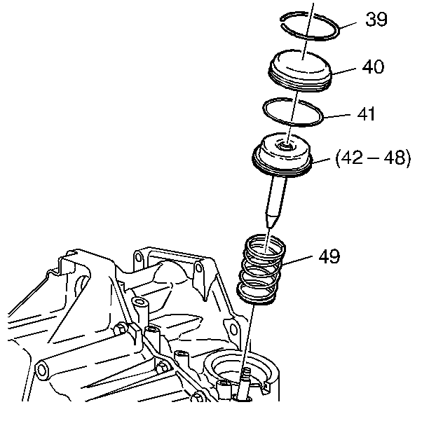
- Remove the reverse servo cover (40).
- Remove the servo assembly (42-48).
- Remove the servo spring (49).


Installation Procedure
- Jack up the driver side (channel plate side) of the car until it is higher than the differential side. This ensures that the reverse band is in the proper location and not cocked to the channel plate side of the case.
- Install the servo spring (49).
- Install the servo assembly (42-48).
- Install the reverse servo cover (40) with new O-ring seal (41).
- Install the snap ring (39).
- Install the throttle body air inlet duct. Refer to Throttle Body Assembly Replacement in Engine Controls.
Important: Follow this procedure exactly or the transaxle will have no reverse gear due to the servo pin missing the band.

