CAMPAIGN: REDUNDANT RADIO CONTROL (STEERING WHEEL RADIO

SUBJECT: REDUNDANT RADIO CONTROL (STEERING WHEEL RADIO CONTROL) CIRCUIT NOT ADEQUATELY PROTECTED
U.S.Campaign Number Cross Reference: 96-C-12
Models: 1996 Pontiac Grand Am Models Equipped with Redundant Radio Control (RPO UK3)
TO, ALL GENERAL MOTORS DEALERS
General Motors of Canada Limited has determined that CERTAIN 1996 Pontiac "Grand Am model vehicles were built with inadequate protection for the Redundant Radio Control circuit. If a certain wire, in the steering column is damaged, the radio controls on the steering wheel may not work because of a short circuit This could result in damage to the control circuit and possibly inadvertent deployment of the driver's side Supplemental Inflatable Restraint (air bag).
To correct this condition, dealers will install a fused jumper harness in the Redundant Radio Control circuit, and replace certain electrical components that may have been exposed to excessive electrical current loads.
VEHICLES INVOLVED:
Involved are the following four (4) 1996 Pontiac Grand Am models equipped with Redundant Radio Control (RPO UK3):
VIN
1G2NE52MXTC700247 1G2NE52M7TC700416 1G2NE52M5TC700348 1G2NE52M5TC700317
NOTE: PLEASE CHECK DCS SCREEN 45 OR YOUR V.I.N. LISTING BEFORE PERFORMING CAMPAIGN TO ENSURE THAT THE VEHICLE IS AFFECTED. ONLY AFFECTED VIN'S WILL BE PAID.
All affected vehicles have been identified by the VIN listing provided to involved dealers with this bulletin. Any dealer not receiving a listing was not shipped any of the affected vehicles.
DEALER CAMPAIGN RESPONSIBILITY:
All unsold new vehicles in dealer's possession and subject to this campaign must be held and inspected/repaired per the Service Procedure of this Campaign Bulletin before owners take possession of these vehicles.
Dealers are to perform this campaign on all involved vehicles at no charge to owners, regardless of kilometres traveled, age of vehicle, or ownership, from this time forward.
Owners of vehicles recently sold from your new vehicle inventory with no owner information indicated on the dealer listing, are to be contacted by the dealer, and arrangements made to make the required correction according to instructions contained in this bulletin. This could be done by mailing to such owners a copy of the owner letter accompanying this bulletin. Campaign follow-up cards should not be used for this purpose, since the owner may not as yet have received the notification letter.
In summary, whenever a vehicle subject to this campaign is taken into your new or used vehicle inventory, or is in your dealership for service in the future, please take the steps necessary to be sure the campaign correction has been made before selling or releasing the vehicle.
CAMPAIGN PROCEDURE:
Refer to Section 4 of the Service Policies and Procedures Manual for the detailed procedure on handling Product Campaigns. Dealers are requested to complete the campaign on all transfers as soon as possible.
OWNER NOTIFICATION:
All owners of record at the time of campaign release are shown on the attached computer listing and have been notified by first class mail from General Motors (see copy of owner letter included with this bulletin). The listings provided are for campaign activity only and should not be used for any other purpose.
PARTS INFORMATION:
Parts required to complete this campaign should be ordered through regular channels, as follows:
Part Number Description Quantity/Vehicle ----------- ----------- ----------------
26036218 Coil - Redundant Radio Control/S.I.R. 1 22653825 Module Inflator 1 16759806 Steering Wheel (Base) 1 16759807 Steering Wheel (Leather) 1 12345493 Thread Lock Compound - Loctite 272 (10 ml) .1ml (Or Equivalent Thread Locking Compound)
THE FOLLOWING PART WILL BE SHIPPED WITH BULLETIN 5N28:
Part Number Description Quantity/Vehicle ----------- ----------- ----------------
NPN Harness-Fused Jumper 1
PARTS AND LABOUR CLAIM INFORMATION:
Credit for the campaign work performed will be paid upon receipt of a properly completed campaign claim card or DCS transmission in accordance with the following:
Repair Time Code Description Allowance ------ ----------- ---------
2A Install Jumper Harness, UK3/SIR Coil, . 8 Inflator Module, Steering Wheel
Time allowance includes 0.1 hour for dealer administrative detail associated with this campaign. Parts credit will be based on dealer net plus 40% to cover parts handling.
An amount of $0.03 will be included in Repair Code 2A for the Thread Lock Compound.
SERVICE PROCEDURE:
1. Turn steering wheel so that the vehicle's wheels are pointing straight ahead.
2. Apply parking brake.
3. Turn ignition switch to "LOCK" position.
4. Remove Supplemental Inflatable Restraint (S.I.R.) fuse from I/P fuse block (AIR BAG fuse -- 10 amp).
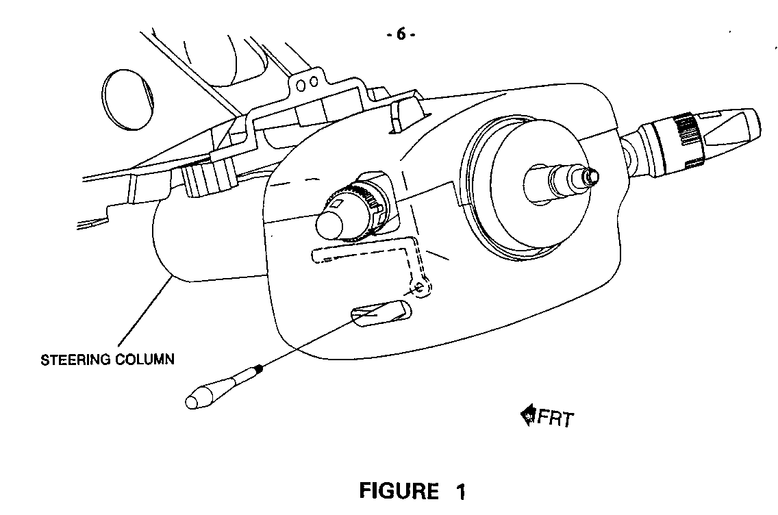
5. Remove tilt steering wheel lever by gripping firmly and turning counterclockwise. See Figure 1.
If necessary, use locking pliers with a piece of rubber, such as a spark plug boot, between the jaws to aid in preventing damage to the lever during removal.
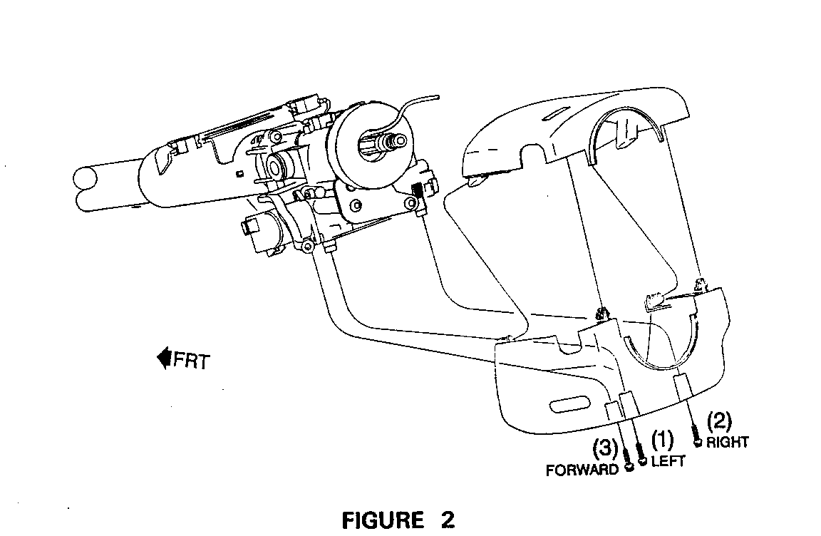
6. Remove upper steering column top cover by disengaging clips. See Figure 2.
7. Remove upper steering column bottom cover (three screws, 7mm hex-head). See Figure 2.
8. Remove LH sound insulator fasteners (one nut, two twist retainers). Disconnect courtesy lamp harness. Disengage S.I.R harness edge clip from panel.
9. Remove LH sound insulator to gain access to S.I.R. lower connector (yellow) and (R.R.C.) lower connector.
10. Remove connector position assurance (CPA) pin from lower S.I.R. connector and disconnect S.I.R. harness.
11. Disconnect R.R.C. harness lower connector.
12. Unlock steering wheel and turn as necessary to gain access to air bag module attaching screws. Remove two screws (10 mm hex) from rear of steering wheel and disengage air bag module from steering wheel.
13. Return steering wheel to the centered, straight-ahead position and turn ignition switch to "LOCK" position.
14. Carefully pull air bag module away from steering wheel and disconnect horn lead ground (black) and the horn lead wire (red).
15. Remove CPA pin from S.I.R. connector (yellow) and disconnect S.I.R. lead.
16. Disconnect R.R.C. lead and remove air bag module from steering wheel.
SERVICE PROCEDURE (Cont'd.): ---------------------------
17. Remove steering wheel nut (21mm).
18. Using steering wheel puller J 1859-03 or BT-61-9, remove steering wheel from steering shaft.
19. Remove two screws (7 mm hex-head) from turn signal switch to gain access to windshield washer switch.
20. Move turn signal switch as necessary to gain access to windshield washer switch screws.
NOTICE: It is not necessary to disconnect the turn signal switch from the wiring harness.
21. Remove two screws (7 mm hex-head) and move the windshield washer switch as required to gain access to the S.I.R. and R.R.C. down-leads.
NOTICE: It is not necessary to disconnect the windshield washer switch from the wiring harness.
22. Using snap ring pliers, remove snap ring from steering shaft.
IMPORTANT: BEFORE PROCEEDING WITH THE REST OF THIS PROCEDURE, OBSERVE THE ROUTING OF THE S.I.R. AND R.R.C. DOWN-LEADS TO ENSURE CORRECT ROUTING OF DOWN-LEADS WHEN INSTALLING THE NEW S.I.R. COIL.
23. Disengage the S.I.R. and R.R.C. down-lead from the steering column wire strap (white).
24. Disengage the S.I.R. and R.R.C. down-lead from the steering column wire clip (black).
25. Remove the S.I.R. coil from the steering shaft.
26. Install new S.I.R. coil to steering shaft, aligning the column horn lead tower with the S.I.R. coil opening.
27. Secure the S.I.R. coil to the steering shaft by reinstalling the snap ring to the steering shaft using snap ring pliers.
IMPORTANT: THE ORANGE ALIGNMENT CLIP ON THE S.I.R. COIL MUST REMAIN ON THE S.I.R. COIL UNTIL THE SNAP RING IS INSTALLED.
28. After the snap ring is reinstalled, remove (break off) die orange alignment clip.
29. Position S.I.R / R.R.C. down-lead into black routing clip under column housing and into the white wire strap.
30. Connect S.I.R. down-lead connector (yellow) to I/P harness. Install CPA pin.
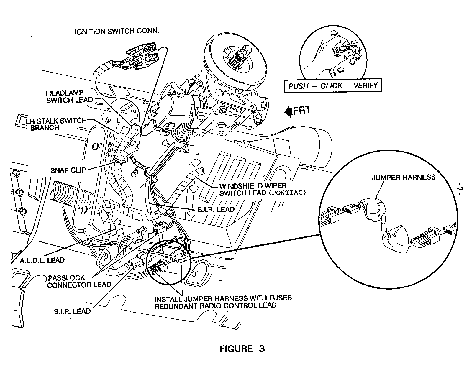
31. Install new fused jumper harness between R.R.C. down-lead connector and I/P harness. See Figure 3.
32. While positioning the new steering wheel to the steering shaft, feed the S.I.R. and R.R.C. up-lead through the steering wheel opening.
SERVICE PROCEDURE (Cont'd.): ---------------------------
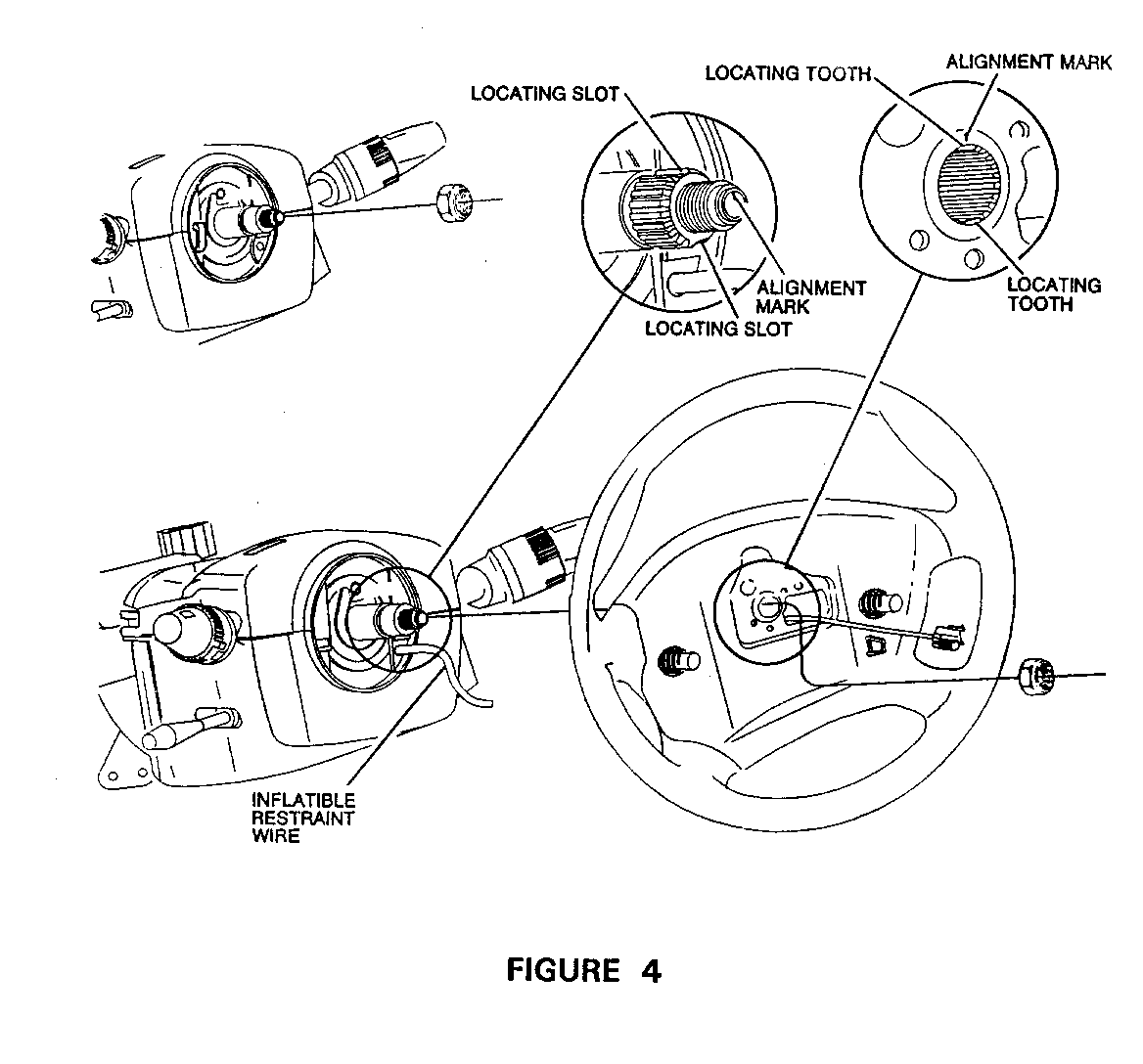
33. Carefully position the new steering wheel assembly to the splined steering shaft and line up the alignment mark on the steering wheel (12 o'clock position) to the alignment mark on the steering shaft. See Figure 4.
34. Push steering wheel onto steering shaft to engage splines.
35. Finger start the steering wheel nut onto the steering shaft Tighten nut to 41 N.m (30 lbs. ft.).
36. Position new air bag module to steering wheel and connect leads as follows:
Connect S.I.R. up-lead to inflator module connector. Install CPA pin.
Connect R.R.C. up-lead to R.R.C. connector.
Connect the horn lead (red).
NOTICE: IN NEW AIR BAG MODULES, HORN GROUND TERMINAL IS GROUNDED IN THE S.I.R. MODULE. THERE IS NO HORN-LEAD GROUND TO CONNECT TO STEERING WHEEL.
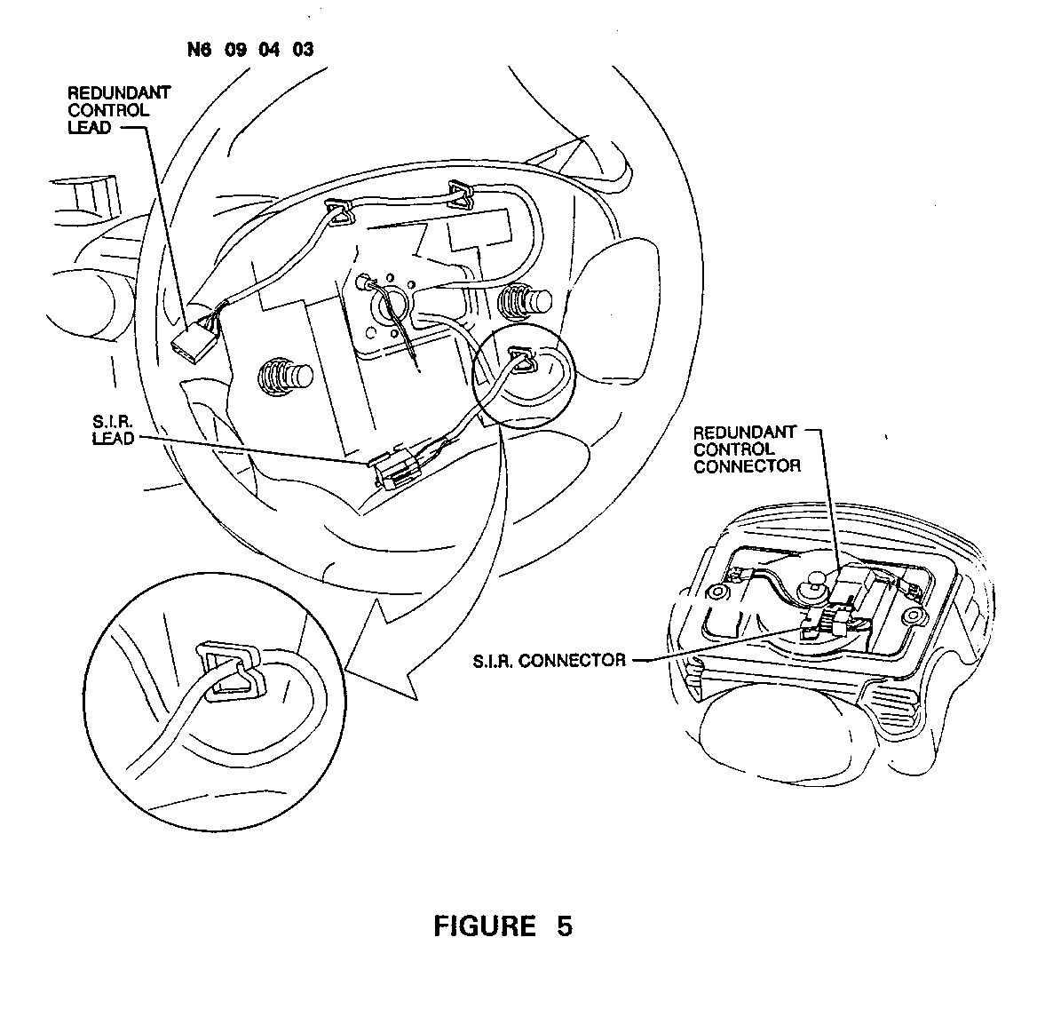
37. Position S.I.R. and R.R.C. up-leads into steering wheel routing clips as shown in Figure 5.
IMPORTANT: THESE LEADS MUST BE ROUTED CORRECTLY. IMPROPER ROUTING OF THESE LEADS CAN RESULT IN PINCHED WIRES AND SHORTED CIRCUITS.
38. Position S.I.R. module onto steering wheel.
39. Unlock steering column and rotate as required to install two S.I.R. module attaching screws (10mm hex) from back of steering wheel. Tighten screws to 9 N.m (6.6 lbs. ft.).
40. Reconnect courtesy lamp harness to courtesy lamp on sound insulator. Replace S.I.R. harness edge clip to edge of panel. Reinstall LH sound insulator (one nut, two twist retainers).
IMPORTANT: MAKE SURE THAT ALL WIRING HARNESSES ARE PROPERLY ROUTED AND NOT PINCHED AT ANY LOCATION.
41. Position windshield washer switch to the steering column upper housing and secure with two screws and tighten to 4 N.m (2.9 lbs. ft. - 35 lbs. in.).
42. Position turn signal switch to steering column housing and secure with two screws. Tighten to 4 N.m (2.9 lbs. ft).
43. Reinstall upper steering column bottom cover with three screws. Tighten to 4 N.m (2.9 lbs. ft.) following sequence shown in Figure 2.
44. Reinstall upper steering column top cover (snap-in). See Figure 2.
45. Apply Loctite #272 or equivalent to tilt steering wheel lever threads. Reinstall tilt steering wheel lever by gripping firmly and turning clockwise. See Figure 1.
46. Reinstall Supplemental Inflatable Restraint (S.I.R.) fuse (AIR BAG fuse).
47. Check S.I.R. system, R.R.C system, and horn for proper function.
48. Install Campaign Identification Label.
INSTALLATION OF CAMPAIGN IDENTIFICATION LABEL
Clean surface radiator upper mounting panel and apply a Campaign Identification Label. Make sure the correct campaign number is inserted on the label. This will indicate that the campaign has been completed.
February 1996
Dear General Motors Customer:
General Motors of Canada Limited has determined that CERTAIN 1996 Pontiac Grand Am model vehicles may have been built with inadequate protection for the Redundant Radio Control circuit. If a certain wire in the steering column is damaged, the radio controls on the steering wheel may not work because of a short circuit. This could result in damage to the control circuit and possibly inadvertent deployment of the driver's side Supplemental Inflatable Restraint (air bag).
To correct this condition, your dealer will install a fused jumper harness in the Redundant Radio Control circuit, and replace certain electrical components that may have been "posed to excessive electrical current loads.
This service will be provided for you at no charge.
Please contact your GM dealer as soon as possible to arrange a service date.
If parts are required, ask your dealer for details regarding their availability. If parts are not in in stock, they can be ordered before scheduling your service date.
This letter identifies your vehicle. Presentation of this letter to your dealer will assist their Service personnel in completing the necessary correction to your vehicle in the shortest possible time.
We are sorry to cause you this inconvenience; however, we have taken this action in the interest of your continued satisfaction with our products.
Customer Support Department General Motors of Canada Limited
General Motors bulletins are intended for use by professional technicians, not a "do-it-yourselfer". They are written to inform those technicians of conditions that may occur on some vehicles, or to provide information that could assist in the proper service of a vehicle. Properly trained technicians have the equipment, tools, safety instructions and know-how to do a job properly and safely. If a condition is described, do not assume that the bulletin applies to your vehicle, or that your vehicle will have that condition. See a General Motors dealer servicing your brand of General Motors vehicle for information on whether your vehicle may benefit from the information.
