Removal Procedure
- Remove the master cylinder reservoir, if necessary. Refer to Master Cylinder Reservoir Replacement .
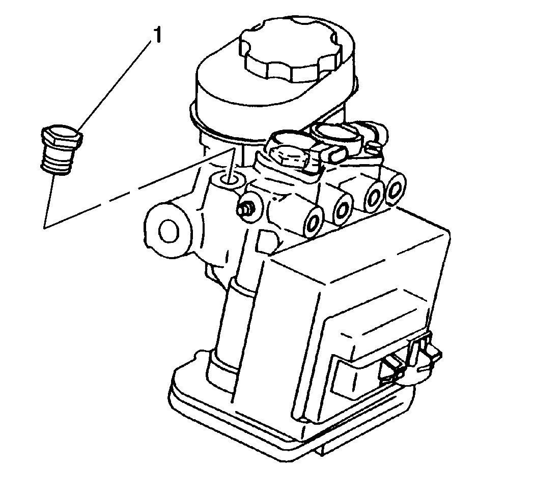
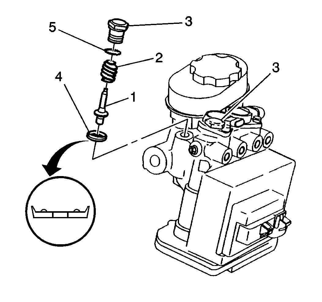
- Remove the proportioner valve caps (1).
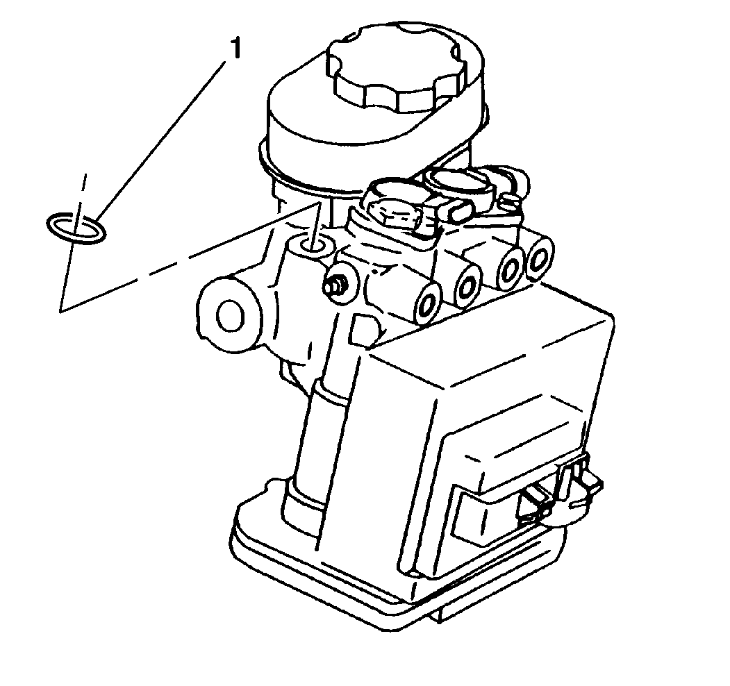
- Remove the proportioner valve cap O-rings. Discard the O-rings (1).
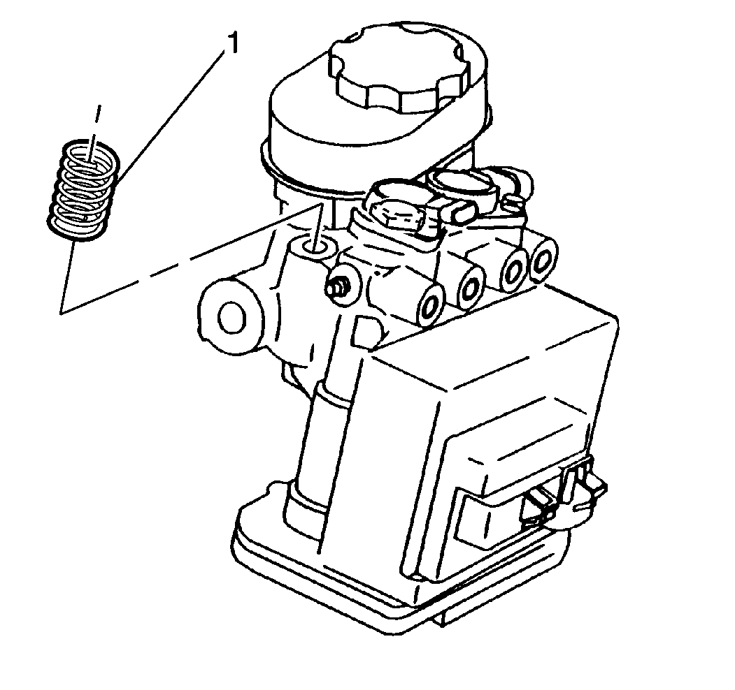
- Remove the proportioner valve piston springs (1).
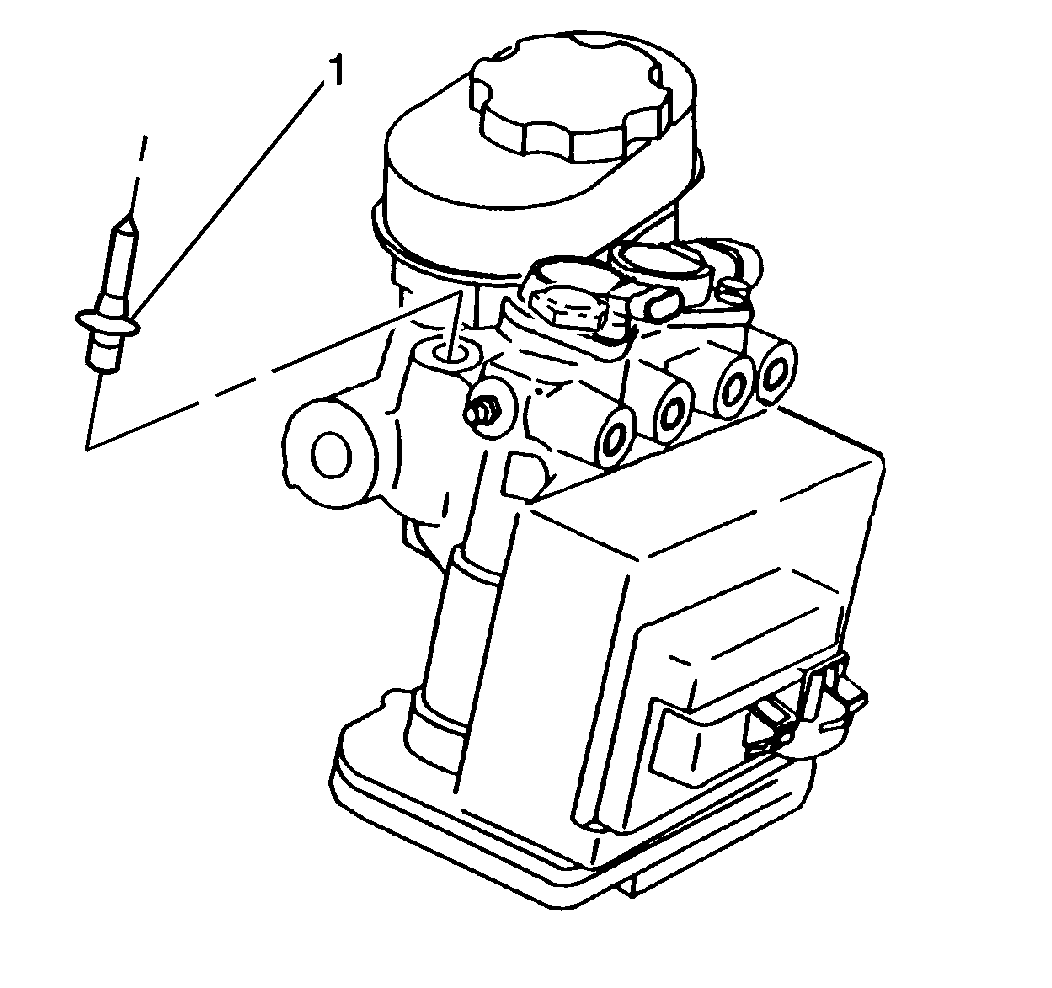
- Remove the proportioner valve pistons (1) using needle nose pliers. Do not scratch or damage the piston stems (1).
- Remove the proportioner valve seals (4) from the proportioner valve pistons (1).
- Clean all parts with denatured alcohol.
- Dry all parts using non-lubricated compressed air.
- Inspect the proportioner valve pistons (1) for corrosion or deformation.
- Replace the parts if defects are found.
Caution: When servicing brake parts, do not create dust by grinding or sanding brake linings, by cleaning brake parts with a dry brush or with compressed air. Many earlier models or aftermarket brake parts may contain asbestos fibers which can become airborne if dust is created during servicing. Breathing dust containing asbestos fibers may cause serious bodily harm. A water dampened cloth or water based solution should be used to remove any dust on brake parts. Equipment is commercially available to perform this washing function. These wet methods will prevent fibers from becoming airborne.
Notice: Use the correct fastener in the correct location. Replacement fasteners must be the correct part number for that application. Fasteners requiring replacement or fasteners requiring the use of thread locking compound or sealant are identified in the service procedure. Do not use paints, lubricants, or corrosion inhibitors on fasteners or fastener joint surfaces unless specified. These coatings affect fastener torque and joint clamping force and may damage the fastener. Use the correct tightening sequence and specifications when installing fasteners in order to avoid damage to parts and systems.
Installation Procedure
- Lubricate the new proportioner valve cap O-rings and proportioner valve seals (1) with silicone grease that is supplied in the repair kit.
- Lubricate the stem of the proportioner valve pistons.
- Connect the new proportioner valve seals (4) on the proportioner valve pistons (1).
- Install the proportioner valve pistons (1) and seals in the master cylinder body.
- Install the proportioner valve piston springs (1) in the master cylinder body.
- Install the new proportioner valve cap O-rings (1) in the grooves in the proportioner valve caps.
- Install the proportioner valve caps (1) in the master cylinder body.
- Install the master cylinder reservoir if removed. Refer to Master Cylinder Reservoir Replacement .
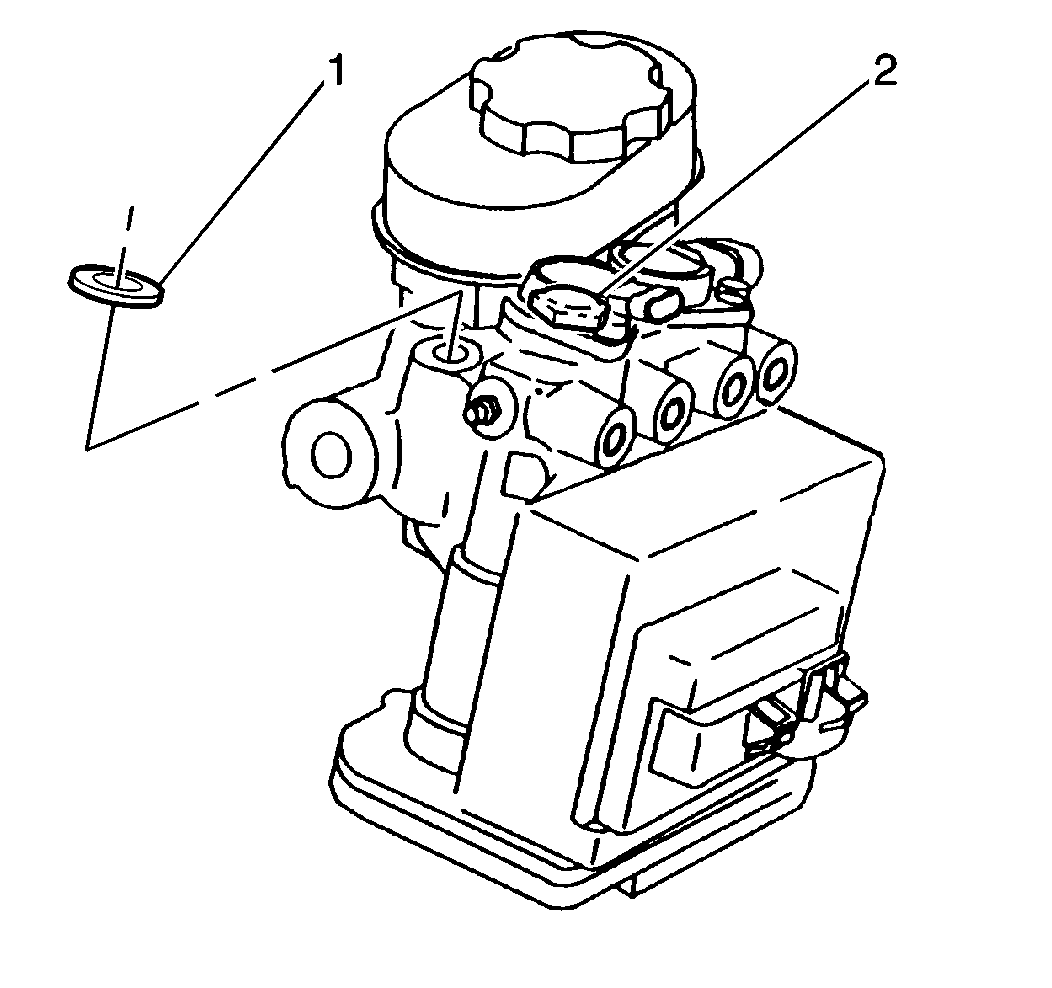

Install the proportioner valve pistons (1) with the seal lips facing upward toward the proportioner valve cap as shown.


Notice: Use the correct fastener in the correct location. Replacement fasteners must be the correct part number for that application. Fasteners requiring replacement or fasteners requiring the use of thread locking compound or sealant are identified in the service procedure. Do not use paints, lubricants, or corrosion inhibitors on fasteners or fastener joint surfaces unless specified. These coatings affect fastener torque and joint clamping force and may damage the fastener. Use the correct tightening sequence and specifications when installing fasteners in order to avoid damage to parts and systems.
Tighten
Tighten the proportioner valve caps to 27 N·m (20 lb ft).
