| Figure 1: |

|
| Figure 2: |

|
| Figure 3: |
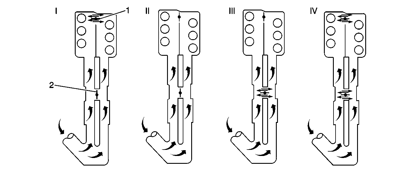
Multi-Ram System Functional Diagram

|
The Multi-Ram
System Functional Diagram shows four stages of air flow: I is Air flow at
idle; II is Air flow at full load, low RPM; III is Air flow at full
load, mid RPM; IV is Air flow at full load, high RPM.
The characteristic torque curve of a normally aspirated engine depends
mainly on how the engine's average pressure changes over the RPM band. The
average pressure is proportional to the volume of the air mass present
in the cylinder when the inlet valve is closed. The design
of the inlet system determines how large an air mass can be
sucked into a cylinder at a given engine RPM.
Thus, he air intake system determines the engine's torque curve. A longer
intake manifold results in higher torque at lower RPM, and a shorter intake
manifold results in higher torque at higher RPM.
The intake manifold on this engine is fitted with 2 valves or flaps
which can be set for 4 different intake manifold lengths. The 4 different
manifold lengths obtainable result in different torque curves
with maximum torque at different engine RPM. The inner valve,
or flap, is located in the intake manifold between the cylinder
heads. When the control module enables the solenoid valve opens and the inner
valve or flap separates the inlet systems of the two banks
of cylinders from each other. The outer flap is located between
the 2 resonating pipes connected to the intake manifold. When
the control module enables the Intake Resonance Switchover Valve the outer
flap opens a connection between the 2 resonating pipes, the active
length of which is thus reduced.
During wide open throttle acceleration from low RPM, the control module
enables the Intake Plenum Switchover Valve. This separates the cylinder banks
from each other and connects each of them to its own resonating
pipe. With the outer flap now closed, the full length of the
resonating pipes is utilized.
When the engine speed reaches 3200 RPM, the control module enables
the Intake Resonance Switchover Valve. This causes the outer flap to open
and reduces the connection between the 2 resonating pipes,
so their active length is reduced.
The control module controls the 2 valves or flaps by means of solenoid
valves and vacuum operated diaphragm units. Using this system allows the torque
curves to overlap in a way that produces the most favorable
results. The solenoid valves are supplied with current via
the main relay and are grounded by the control module.
When engine speed reaches 4100 RPM, the control module opens
the circuit to the Intake Plenum Switchover Valve, so that the 2 inlet systems
(1 for each bank of cylinders) are connected to each other,
and the effective pipe length is the shortest possible.
At speeds below 4100 RPM and with a throttle valve angle less
than 50 degrees, the inner flap is always open. This keeps the idle
air control valve's supplementary air distributed equally between
the cylinders.


