Removal Procedure
Tools Required
J 36660-A Torque/Angle Meter
Caution: To avoid any vehicle damage, serious personal injury or death when major components are removed from the vehicle and the vehicle is supported by a hoist, support the vehicle with jack stands at the opposite end from which the components are being removed and strap the vehicle to the hoist.
- Raise and support the vehicle. Refer to Lifting and Jacking the Vehicle in General Information.
- Remove the front wheel assembly. Refer to Tire and Wheel Removal and Installation in Tires and Wheels.
- Remove the wheel speed sensor wiring from the strut assembly.
- Remove the brake wear indicator wires from the strut assembly.
- Remove the brake flex hose clip from the strut assembly.
- Remove the brake flex hose from the strut assembly.
- Remove the brake caliper assembly bolts from the steering knuckle.
- Remove the brake caliper assembly from the steering knuckle. Do not open the brake hydraulic system.
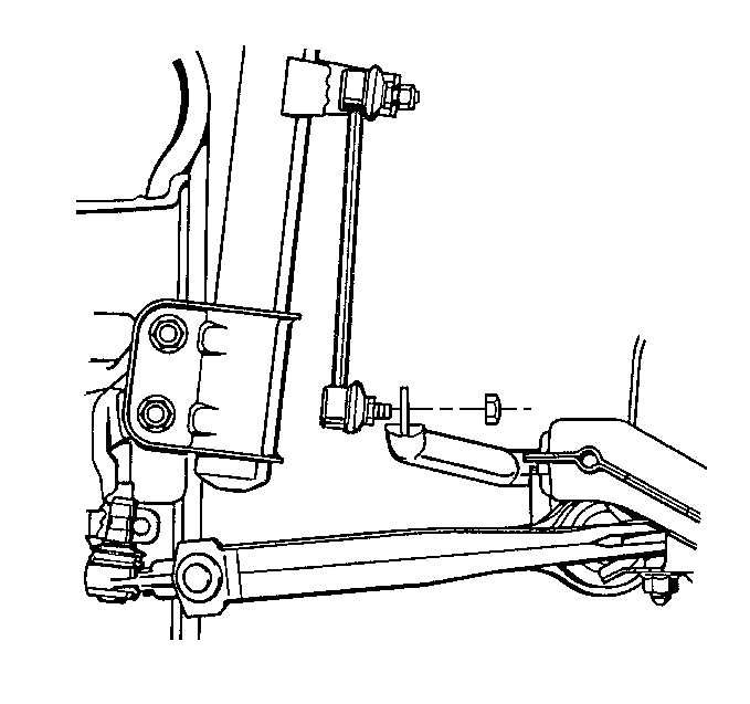
- Remove the stabilizer shaft link nut.
- Remove the stabilizer shaft link from the strut assembly.
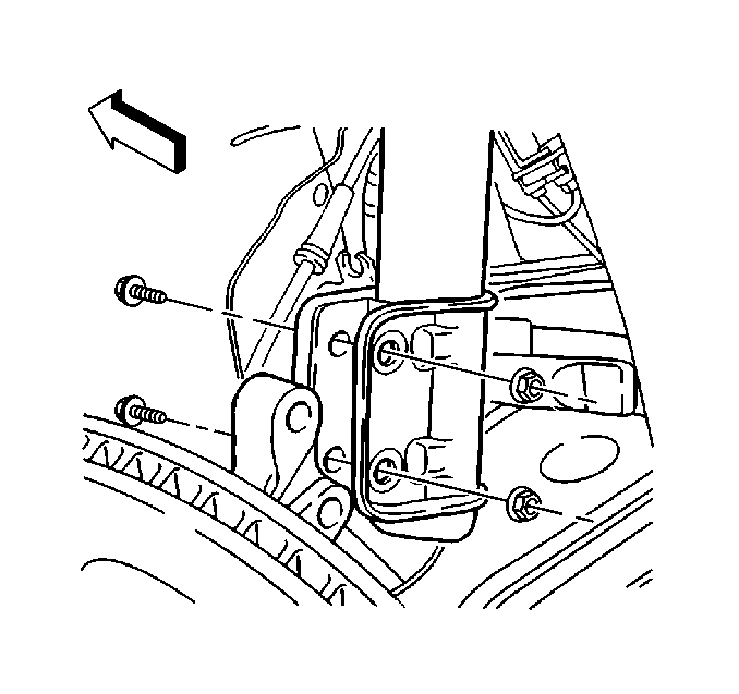
- Remove the lower strut mounting bolts from the steering knuckle.
- Lower the vehicle.
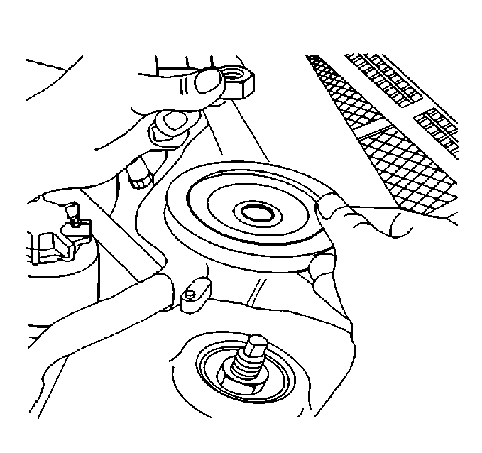
- Remove the upper support plate protective cap.
- Remove the upper support plate nut.
- Remove the upper support plate.
- Remove the strut assembly from the wheel well.
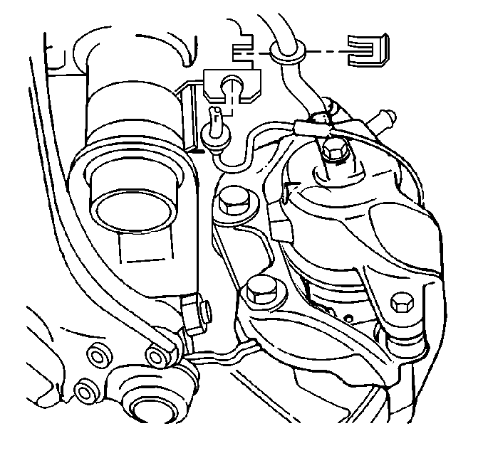
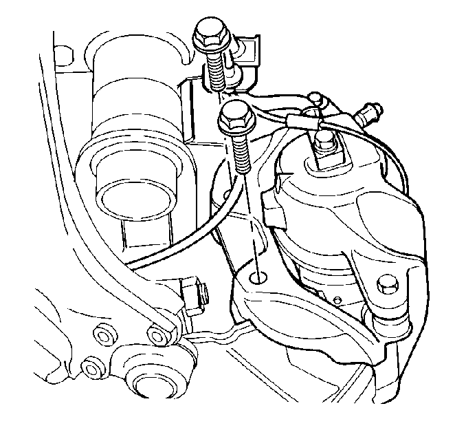
Important: Support the brake caliper assembly. Do NOT allow the assembly to hang freely or damage may occur to the flex hose.
Installation Procedure
- Install the strut assembly into the strut tower through the wheel well.
- Install the upper support plate.
- Install the upper support nut.
- Install the protective cap for the upper support nut.
- Raise the vehicle.
- Install the steering knuckle to the strut.
- Install the steering knuckle to the strut bolts (use new bolts installed form the front toward the rear of the vehicle).
- Tighten the steering knuckle to the strut bolts until snug. Do NOT tighten the bolts to specifications until after you have made the final camber corrections.
- Install the stabilizer shaft link to the strut assembly.
- Install the stabilizer shaft link nut.
- Install the brake caliper assembly to the steering knuckle and tighten the bolts using J 36660-A .
- Install the brake flex hose to the strut assembly.
- Install the clip to the strut assembly.
- Install the wheel speed sensor wire to the strut assembly.
- Install the brake wear indicator wires to the strut assembly.
- Install the front wheel assembly. Refer to Tire and Wheel Removal and Installation in Tires and Wheels.
- Lower the vehicle.
- Adjust the wheel alignment. Refer to Wheel Alignment Measurement in Wheel Alignment.

Notice: Use the correct fastener in the correct location. Replacement fasteners must be the correct part number for that application. Fasteners requiring replacement or fasteners requiring the use of thread locking compound or sealant are identified in the service procedure. Do not use paints, lubricants, or corrosion inhibitors on fasteners or fastener joint surfaces unless specified. These coatings affect fastener torque and joint clamping force and may damage the fastener. Use the correct tightening sequence and specifications when installing fasteners in order to avoid damage to parts and systems.
Tighten
Tighten the upper support nut to 55 N·m (41 lb ft).


Tighten
Tighten the stabilizer shaft link nut to 65 N·m (48 lb ft).

Important:
• Run a M12 x 1.5 tap through the holes for
the brake caliper assembly bolts to clean out the old locking compound. • Use new bolts for the brake caliper assembly connection to the
steering knuckle. • Coat the bolts with locking compound. Use GM P/N 12345493
Goodwrench 272 Threadlocker, or equivalent.
Tighten
Tighten the brake caliper assembly bolts to 95 N·m (70 lb ft)
+ 37 degrees.

