Removal Procedure
Tools Required
| • | J 22912-B Rear Pinion Bearing Remover |
| • | J 42099 Center Bearing Installer |
- Remove the propeller shaft. Refer to Two-Piece Propeller Shaft Replacement in this section.
- Remove the propeller shaft slip yolk boot strap and remove the boot.
- Mark the halves of the propeller shaft near the slip joint.
- Separate the propeller shaft halves.
- Remove the front propeller shaft bearing retaining ring (1) from the journal.
- Remove the slinger (1).
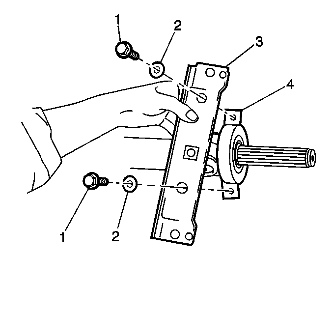
- Remove the bracket bolts (1) and washers (2).
- Remove the bracket (3) from the insulator (4).
- Install the J 22912-B on the shaft.
- Support the J 22912-B in a vice.
- Drive the propeller shaft from the bearing using a deadblow hammer.
- Remove the rear slinger.
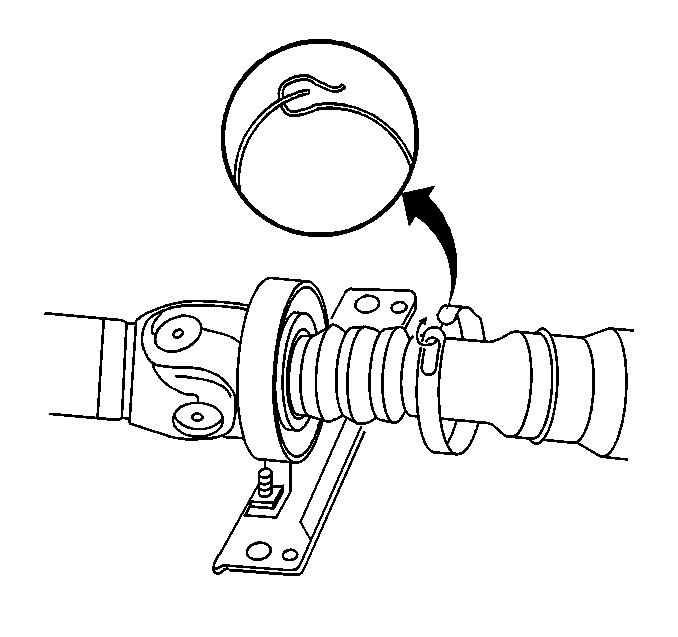
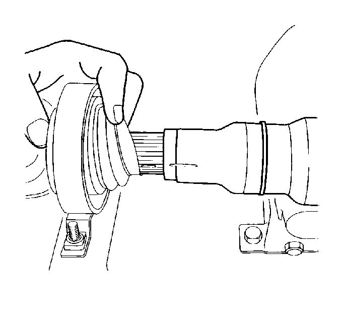
Important: Marking the propeller shaft must be performed to ensure correct spline alignment, as well as, retaining the production balance of the propeller shaft assembly.
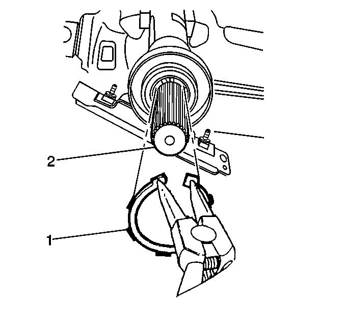
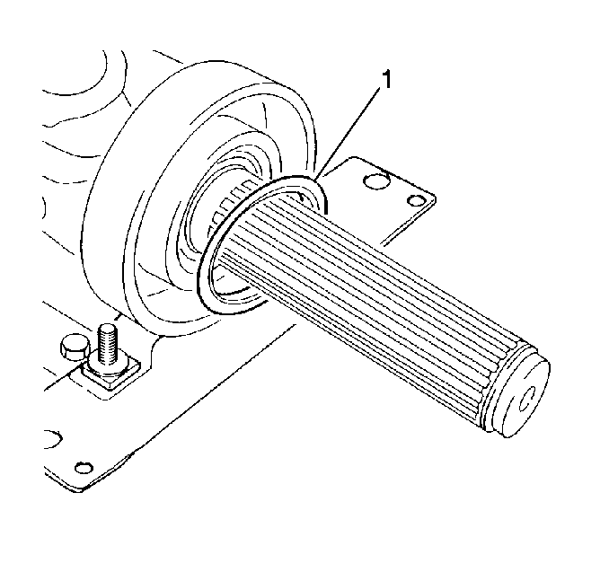
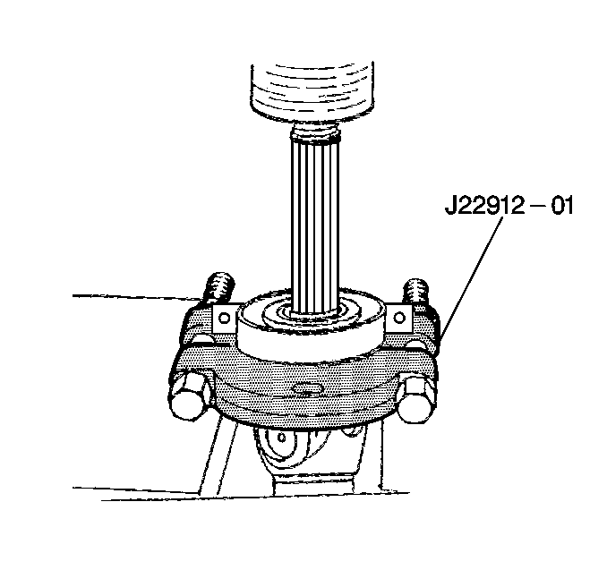
Important: During the next step, only tighten the J 22912-B enough so that the tool supports the inner race and does not clamp onto the journal. Damage to the journal will occur.
Installation Procedure
- Install the rear slinger.
- Using J 42099 , install the bearing (1) onto the journal.
- Install the bracket (3) to the insulator (4).
- Install the bracket bolts (1) and washers (2).
- Install the slinger (1).
- Install the retaining ring (1).
- Install the slip yolk boot onto the propeller shaft.
- Clean the slip yolk journal mating surfaces.
- Lubricate the slip yolk journal splines with grease, GM P/N 12345740 or equivalent.
- Join the propeller shaft halves.
- Install the slip yolk boot strap.
- Install the propeller shaft. Refer to Two-Piece Propeller Shaft Replacement in this section.
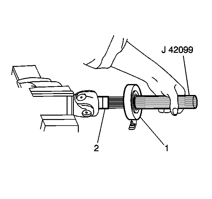

Notice: Use the correct fastener in the correct location. Replacement fasteners must be the correct part number for that application. Fasteners requiring replacement or fasteners requiring the use of thread locking compound or sealant are identified in the service procedure. Do not use paints, lubricants, or corrosion inhibitors on fasteners or fastener joint surfaces unless specified. These coatings affect fastener torque and joint clamping force and may damage the fastener. Use the correct tightening sequence and specifications when installing fasteners in order to avoid damage to parts and systems.
Tighten
Tighten the bolts to 22 N·m (16 lb ft).


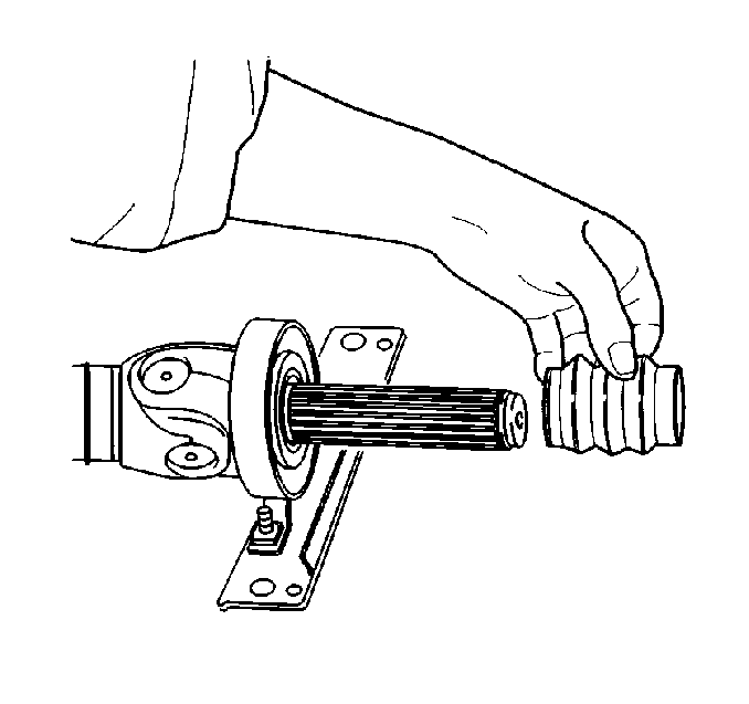

Important: When reassembling the propeller shaft halves, align both markings previously made as well as the blind spline of the journal. If the propeller shaft halves are aligned properly, they should join with little effort. Do not force the halves together.

