Disassembly Procedure
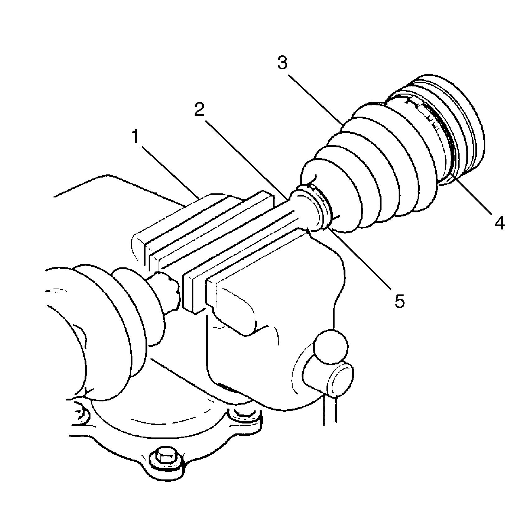
- Clamp the halfshaft assembly into a vise (1) which has non-marring inserts.
- Remove the large boot retaining clamp (4) from the inboard cross groove joint with a side cutter.
- Discard the large boot retaining clamp (4).
- Remove the small boot retaining clamp (5) from the halfshaft bar (2) with side cutter.
- Discard the small boot retaining clamp (5).
- Slide the boot (3) up the halfshaft bar (2) away from the joint.
- Wipe grease from face of cross-groove inner race.
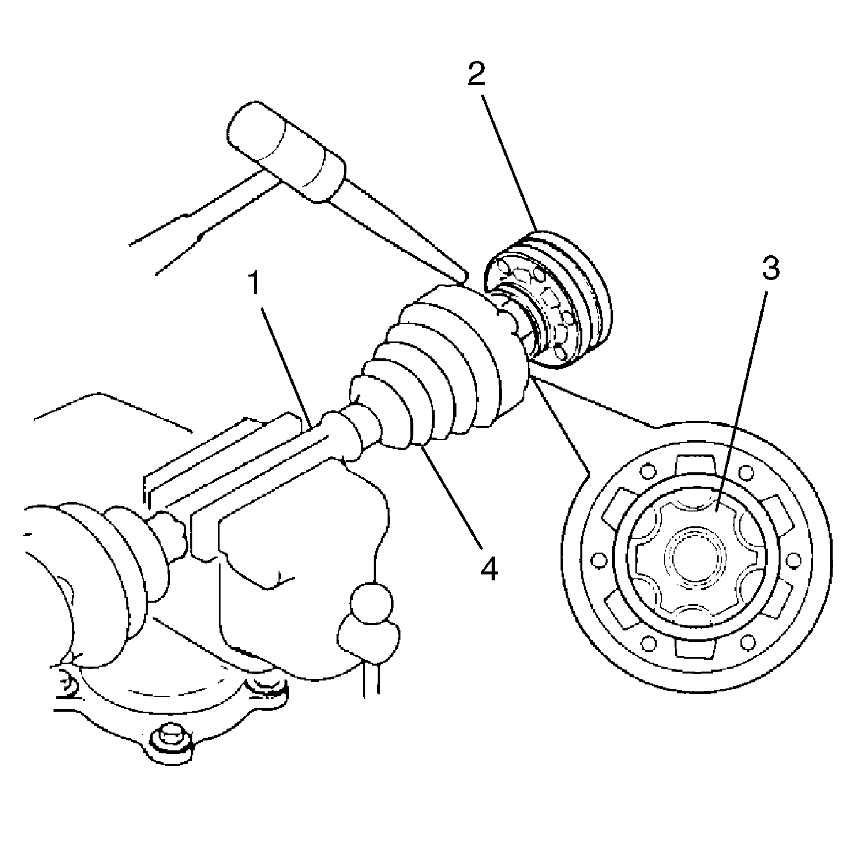
- Use a brass drift and a hammer to tap on the inner race (3) of the cross groove (2). This may take several taps before the cross groove (2) assembly disconnects from the halfshaft bar (1). Take care not to damage the inner race (3).
- Remove the retaining ring from the halfshaft bar (1).
- Discard the retaining ring.
- Remove the old boot (4) from the halfshaft bar (1).
- Discard the old boot (4).
- Check the inboard joint for any visible damage or wear. Replace if necessary.


Important: Never reuse the retaining ring.
Assembly Procedure
Tools Required
J 35910 Drive Axle Seal Clamp Pliers
- Pack the inboard cross groove joint with half the grease provided in the service kit.
- Place new small boot retaining clamp on neck of boot. Do not crimp.
- Position the new large boot retaining clamp around the joint boot.
- Clean the halfshaft bar. Use a wire brush to remove any rust in the boot mounting area (grooves).
- Place the boot onto the halfshaft bar towards the outboard joint.
- Place the new retaining ring onto the halfshaft bar.
- While supporting the outboard cross groove assembly, place the halfshaft assembly onto the arbor press with the inboard cross groove assembly under the press head.
- Place a block of wood over the inboard cross groove assembly before lowering the press head. This will protect the housing from any damage.
- Lower the arbor press head onto the inboard cross groove assembly until the press cannot move any further.
- Remove the halfshaft assembly from the arbor press.
- Place the halfshaft assembly into the vise.
- Slide the boot back toward the inboard joint and place the neck of the joint boot into the boot groove on the halfshaft bar.
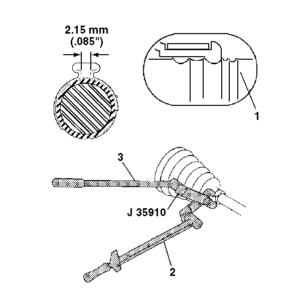
- Crimp the small retaining clamp by using J 35910 with a breaker bar (3) and torque wrench (2).
- Check the gap dimensions. Continue tightening until the gap correct dimension is reached.
- Place the remaining grease into the inboard boot.
- Slide large diameter of the boot with the large boot retaining clamp in place over the lip of the inboard joint housing.
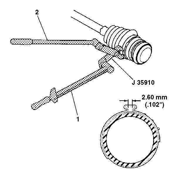
- Clamp the large boot retaining clamp by using J 35910 with a breaker bar (2) and a torque wrench (1).
- Check the gap dimensions. Continue tightening until the gap correct dimension is reached.


Notice: Use the correct fastener in the correct location. Replacement fasteners must be the correct part number for that application. Fasteners requiring replacement or fasteners requiring the use of thread locking compound or sealant are identified in the service procedure. Do not use paints, lubricants, or corrosion inhibitors on fasteners or fastener joint surfaces unless specified. These coatings affect fastener torque and joint clamping force and may damage the fastener. Use the correct tightening sequence and specifications when installing fasteners in order to avoid damage to parts and systems.
Tighten
Tighten the clamp to 136 N·m(100 lbs ft).
Important: The boot must not be dimpled, stretched or out of shape in any way. If the boot is not shaped correctly, equalize pressure on the boot and shape the boot properly by hand.

Tighten
Tighten the clamp to 176 N·m (130 lbs ft).
