For 1990-2009 cars only
Removal Procedure
Tool Required
J 29803-A ISO Flaring Tool
- Obtain the recommended tubing and steel fitting nuts of the correct size. Use the outside diameter of the tubing to specify the size.
- Cut the tubing to length. Use a string to measure the old pipe and add 3 mm (1/8 in) to determine the correct length for each ISO flare.
- Cut the end square
- Use a de-burring tool to chamfer inside and outside diameter of the tubing.
- Remove all traces of lubricant and/or metal chips from the tubing.
- Ensure the fittings are installed on the tubing before starting the flare.
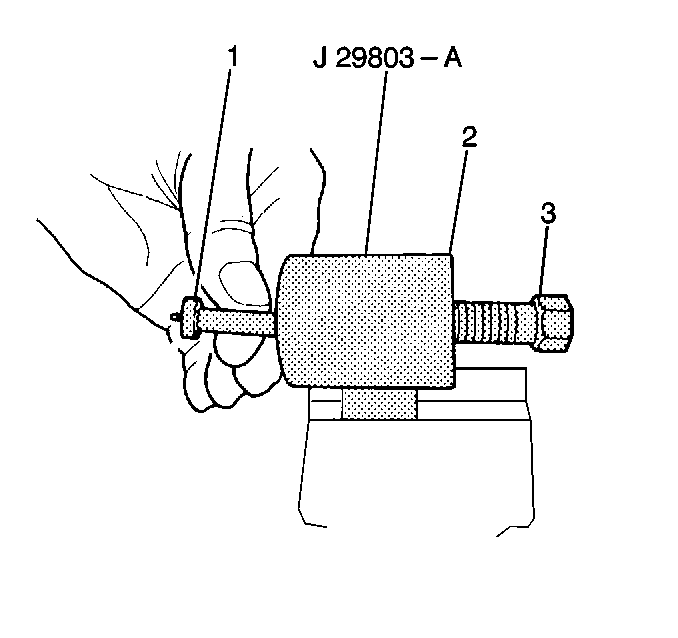
- Clamp the flaring tool body (2) in a vise.
- Select the correct size collet and forming mandrel for the tube size used.
- Insert the proper forming mandrel (1) into the tool body.
- Thread in the forcing screw (3) until it makes contact and begins to move the forming mandrel (1) while holding the mandrel (1) in place with your finger.
- Turn the forcing screw back one complete turn when contact is made.
- Slide the clamping nut (1) over the tubing into the correct collet. Leave approximately 19 mm (3/4 in) of tubing extending out the collet.
- Insert the assembly into the tool body. The tube end must contact the face of the forming mandrel.
- Tighten the clamping nut into the tool body very tight or the tube may push out.
- Wrench tighten the forcing screw in until it bottoms. Do not overtighten the forcing screw or the flare may become over-sized.
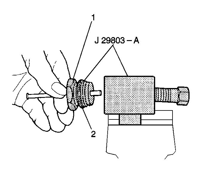
- Back the clamping nut (1) out of the tool body.
- Disassemble the clamping nut (1) and collet (2).
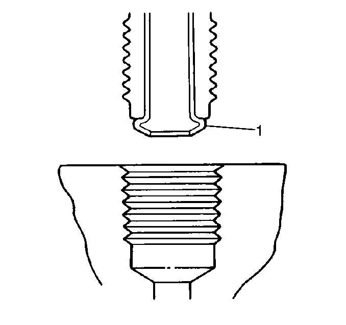
- The flare is now ready for use.
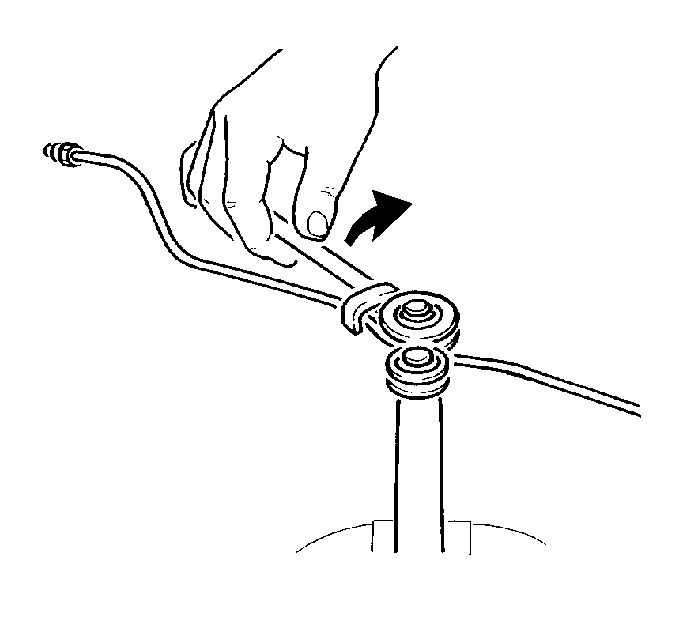
- Use a tube bender to bend the new pipe to match the old pipe.
- Ensure to maintain the following clearances:


| • | Maintain the minimum clearance of 19 mm (3/4 in) to all moving components. |
| • | Maintain the minimum clearance of 13 mm (1/2 in) to all vibrating components. |
| • | Maintain the minimum clearance of 7 mm (1/4 in) to any shielded lines, unless clipped to a component. |
