Removal Procedure
- Release the parking brake if applied.
- Raise and suitably support the vehicle. Refer to Lifting and Jacking the Vehicle in General Information.
- Remove the brake caliper. Refer to Brake Caliper Replacement in Disc Brakes.
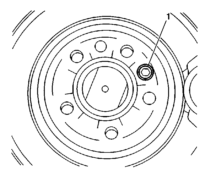
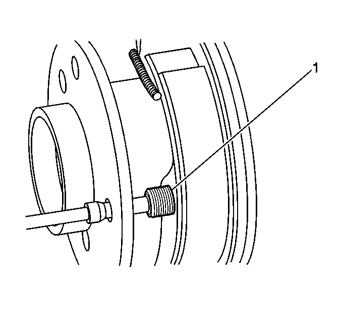
- Remove the rotor set screw (1).
- Remove the brake rotor from the hub.
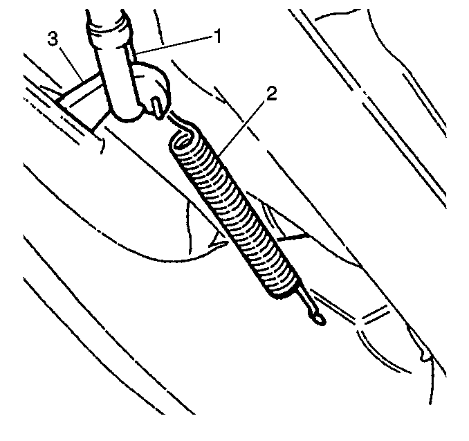
- Remove the parking brake cable return spring (2) from the parking brake lever (3) and backing plate.
- Remove the parking brake cable (1) from the parking brake lever (3).
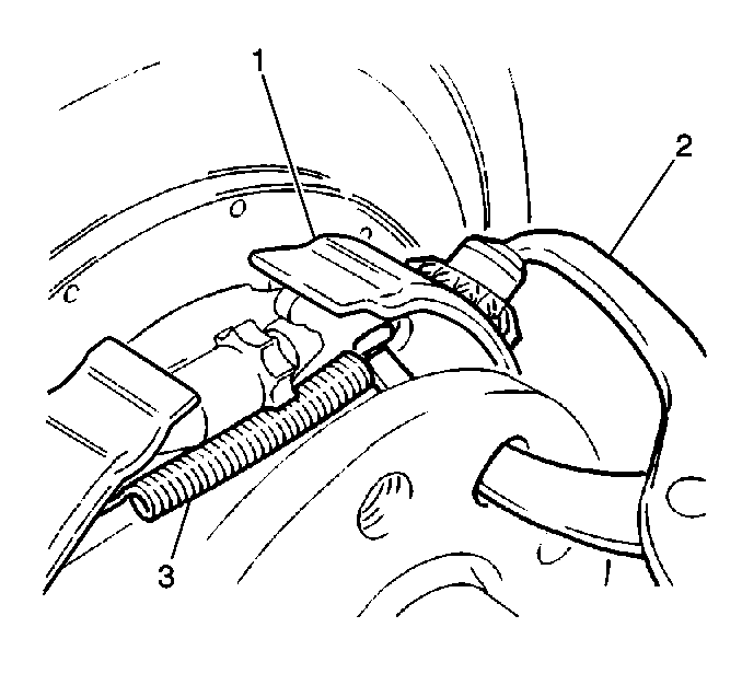
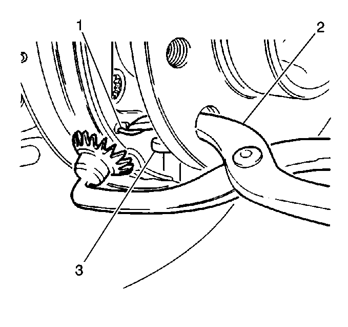
- Use brake spring pliers (2) to remove the parking brake shoe upper return spring (1) from the parking brake shoe (3).
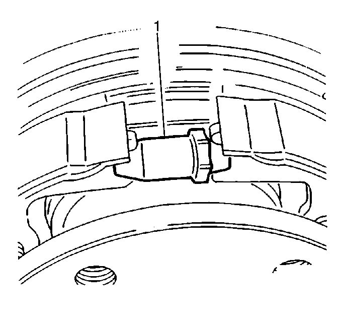
- Remove the parking brake adjuster (1).
- Use brake spring pliers (2) to remove the parking brake shoe lower return spring (1) from the parking brake shoe (3).
- Rotate the wheel bearing hub flange to the center largest cutout over the parking brake shoe retaining pin.
- With a ¼-inch drive, deep well socket that fits over the retaining pin, press down on the brake shoe retaining cup to remove the following components:
- Repeat steps for the opposing brake shoe retaining spring, retainer, and pin removal.
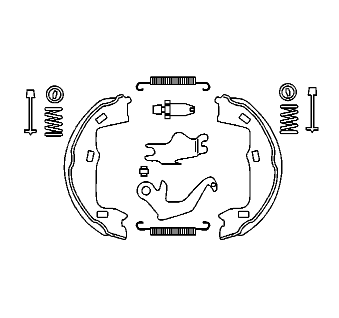
- Remove the parking brake shoes.
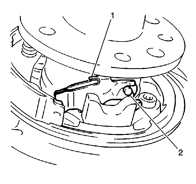
- Remove the parking brake lever strut (1) and pivot pin (2).
- Remove the parking brake lever.
- Clean all the removed components.
- Inspect all the removed components for wear and/or damage.
- Replace any worn and/or damaged parts.
Important: Replace the parking brake shoes in complete axle sets only.
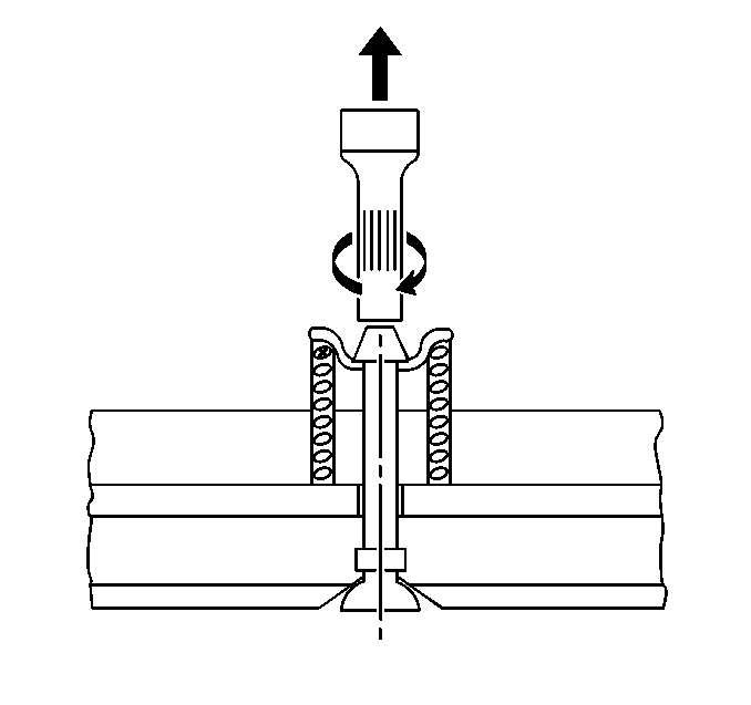
| • | To remove the parking brake shoe retaining spring. |
| • | To remove the parking brake shoe retaining cup. |
Installation Procedure
- Lubricate the parking brake adjuster screw and its threads completely.
- Install the parking brake shoe.
- Rotate the wheel bearing hub flange to the center largest cutout over the parking brake shoe retaining pin.
- With a ¼-inch drive, deep well socket that fits over the retaining pin, press down on the brake shoe retaining cup to install the following components:
- Repeat steps to install the opposing brake shoe.
- Install the parking brake lever.
- Install the parking brake lever strut with the pivot pin.
- Use brake spring pliers (2) to install the parking brake shoe lower return spring.
- Install the self adjuster (1) between the shoes.
- Use brake spring pliers (2) to install the parking brake shoe upper return spring (1).
- Extend the parking brake adjuster until the brake shoes just touch the brake drum.
- Install the brake rotor onto the wheel bearing hub.
- Install the parking brake cable (1) onto the parking brake lever (3).
- Install the parking brake cable return spring (2) to the parking brake lever (3) and the brake backing plate.
- Install the brake rotor set screw (1).
- Install the brake caliper. Refer to Brake Caliper Replacement in Disc Brakes.
- Repeat the above procedure for the opposite side of the vehicle.
- Test the parking brake operation and state of adjustment.
| • | To install the parking brake shoe retaining spring (1). |
| • | To install the parking brake shoe retaining cup. |


Notice: Use the correct fastener in the correct location. Replacement fasteners must be the correct part number for that application. Fasteners requiring replacement or fasteners requiring the use of thread locking compound or sealant are identified in the service procedure. Do not use paints, lubricants, or corrosion inhibitors on fasteners or fastener joint surfaces unless specified. These coatings affect fastener torque and joint clamping force and may damage the fastener. Use the correct tightening sequence and specifications when installing fasteners in order to avoid damage to parts and systems.
Tighten
Tighten the brake rotor set screw (1) to 4 N·m (35 lb in).
Important: Ensure the rear wheels still turn on the 4th notch of the parking brake application. Ensure the rear wheels are tight on the 7th notch. Refer to Parking Brake Shoe Adjustment .
