Oil Cooler Pipes Replacement Rear Section
Removal Procedure
The hose portion of the pipes can be replaced without replacing the
entire pipe. Install the replacement hose using clamps of the appropriate
size.
The rear pipe on the transmission feeds to the oil cooler. The front
pipe on the transmission returns fluid to the transmission.
Rear Section
- Raise and suitably support the vehicle. Refer to
Lifting and Jacking the Vehicle
in General Information.
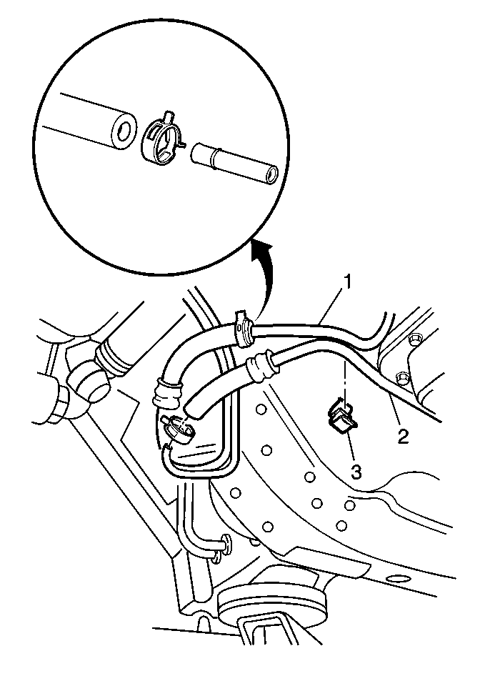
- Remove the center oil
cooler hoses inlet and outlet pipe hoses from oil cooler inlet and outlet
pipes.
| • | Squeeze the clamps away from connection. |
| • | Slide the clamps away from the connection. |
| • | Remove the hoses from pipes. |
- Remove the retainer from
oil cooler inlet and outlet pipes.
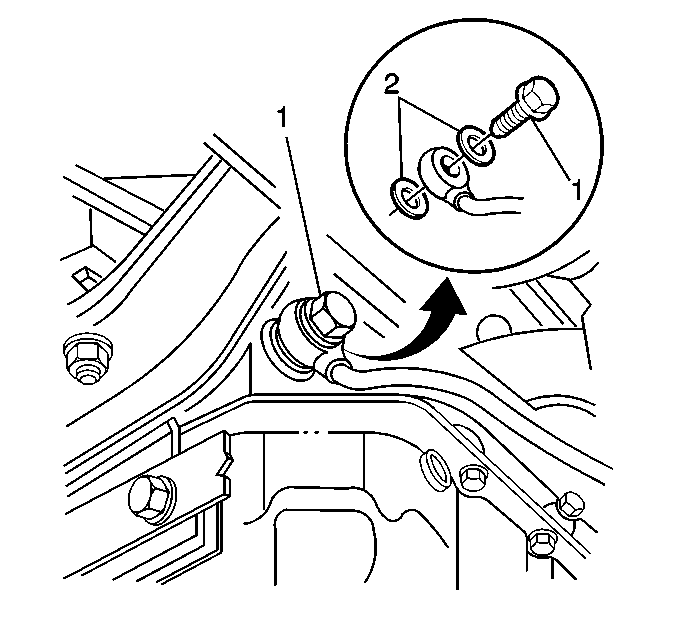
- Remove the oil cooler inlet pipe fitting and seals (2) from transmission.
Discard seals.
- Remove the oil cooler inlet pipe from transmission.
- Remove oil cooler outlet pipe fitting from transmission.
- Remove oil cooler outlet pipe from transmission.
Installation Procedure

- Install the oil cooler
outlet pipe to transmission.
- Install the oil cooler outlet pipe fitting to transmission.
Notice: Use the correct fastener in the correct location. Replacement fasteners
must be the correct part number for that application. Fasteners requiring
replacement or fasteners requiring the use of thread locking compound or sealant
are identified in the service procedure. Do not use paints, lubricants, or
corrosion inhibitors on fasteners or fastener joint surfaces unless specified.
These coatings affect fastener torque and joint clamping force and may damage
the fastener. Use the correct tightening sequence and specifications when
installing fasteners in order to avoid damage to parts and systems.
Tighten
Tighten the oil cooler outlet pipe fitting to 30 N·m (22 lb ft).
- Install the oil cooler inlet pipe to transmission.
- Install the oil cooler pipe seals inlet fitting.
Tighten
Tighten the oil cooler inlet pipe fitting to 25 N·m (18 lb ft).
- Install the retainer to oil cooler inlet and outlet pipes.
- Install the center oil cooler inlet and outlet pipe hoses to oil
cooler inlet and outlet pipes.
| • | Connect the hoses to pipes. |
| • | Slide the clamps into position. |
- Lower the vehicle.
- Check the transmission fluid level. Refer to
Transmission Fluid Check
.
Oil Cooler Pipes Replacement Middle Section
Removal Procedure
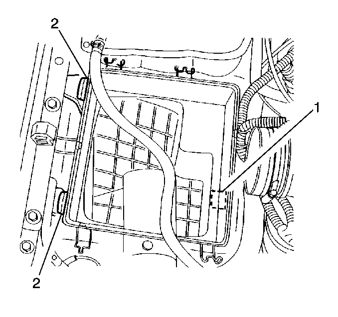
- Remove the air filter
housing.
| 1.3. | Unseat from the inner grommets (2). Then from the outer grommets
(1). |
- Remove the generator cooling duct.
- Remove the fuel vapor fresh air inlet hose. This hose connects
to the fuel vapor filter (passenger side of engine compartment) extends down
and wraps around the center inlet and outlet pipes.
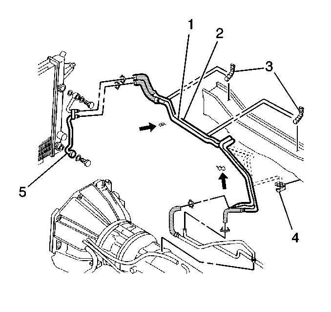
- Remove the center inlet
and outlet pipe hoses from pipe (5) at radiator.
| 4.2. | Slide away from connection |
| 4.3. | Disconnect the hoses from pipe |
- Remove the center inlet and outlet pipes from upper retainers
on body.
- Raise and suitably support the vehicle. Refer to
Lifting and Jacking the Vehicle
in General Information.
- Remove the center inlet and outlet pipe hoses from inlet and out
pipes.
| 7.2. | Slide away from connection |
| 7.3. | Remove the hoses from pipes |
- Remove the pipes from retainer on body.
- Remove the pipes from vehicle. Remove pipes from bottom of vehicle.
Installation Procedure

- Install the pipes (1,
2) to the vehicle. Install pipes from bottom of vehicle.
- Install the pipes to retainer on body.
- Install the inlet and outlet pipe hoses to oil cooler inlet and
outlet pipes.
| • | Position the hoses on the pipes |
| • | Slide the clamps over the hoses |
- Lower the vehicle.
- Install the center inlet and outlet pipes to retainers on body.
- Install the center inlet and outlet pipe hoses to pipe at radiator.
| • | Position the hoses to pipes |
| • | Slide the clamps into position |
- Install the fuel vapor fresh air inlet hose. This hose connects
to the fuel vapor filter (passenger side of engine compartment) extends down
and wraps around the fluid cooler lines.
- Install the generator cooling duct.

- Install the air filter
housing.
| • | Seat the housing onto the grommets (2). Then to inner grommet
(1). |
- Check the transmission fluid level. Refer to
Transmission Fluid Check
.
Oil Cooler Pipes Replacement Front Section
Removal Procedure

- Remove the air filter
housing.
| • | Unseat from the grommets (1, 2). |
- Remove the generator cooling duct.
- Remove the center inlet and outlet pipe hoses from oil cooler
pipe.
| • | Slide the clamps away from the connection. |
| • | Disconnect the hoses from pipe. |
- Remove the upper pipe fitting and seals from radiator. Discard
seals.
- Raise and suitably support the vehicle. Refer to
Lifting and Jacking the Vehicle
in General Information.
- Remove the lower pipe fitting and seals from radiator. Discard
seals.
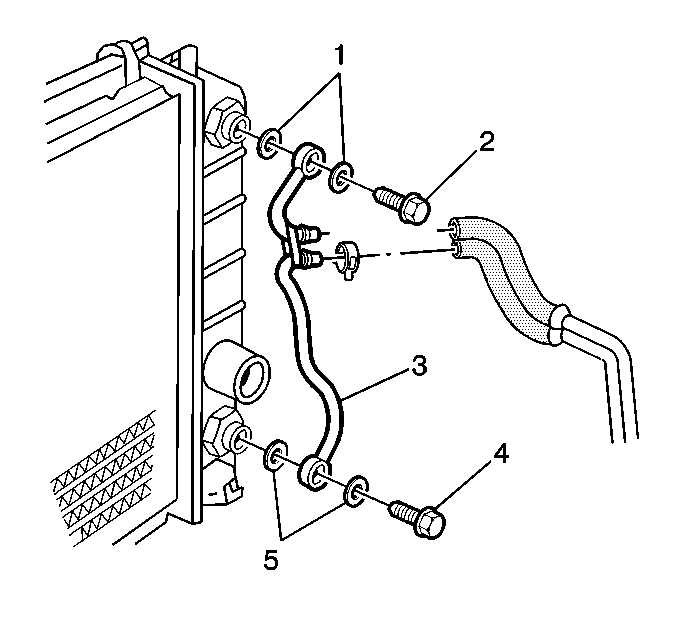
- Remove the front oil cooler
pipe (3) from vehicle.
Installation Procedure

- Install the front oil
pipe (3) to vehicle.
- Install the lower pipe fitting and new seals to radiator.
Notice: Use the correct fastener in the correct location. Replacement fasteners
must be the correct part number for that application. Fasteners requiring
replacement or fasteners requiring the use of thread locking compound or sealant
are identified in the service procedure. Do not use paints, lubricants, or
corrosion inhibitors on fasteners or fastener joint surfaces unless specified.
These coatings affect fastener torque and joint clamping force and may damage
the fastener. Use the correct tightening sequence and specifications when
installing fasteners in order to avoid damage to parts and systems.
Tighten
Tighten the lower pipe fitting to 25 N·m (18 lb ft).
- Lower the vehicle.
- Install the upper pipe fitting and new seals to radiator.
- Install the upper pipe fitting bolt.
Tighten
Tighten the upper pipe fitting to 25 N·m (18 lb ft).
- Install the center oil cooler pipe hoses to pipe.
| • | Install the hoses to pipes. |
| • | Slide the clamps into position. |
- Install the generator cooling duct.

- Install the air filter
housing.
| • | Seat the housing onto the grommets (1, 2). |
- Check the transmission fluid level. Refer to
Transmission Fluid Check
.


