Removal Procedure
- Disconnect the negative battery cable.
- Remove the windshield wiper assembly. Refer to Windshield Wiper Transmission Replacement in Wiper/Washer System.
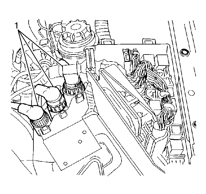
- Remove the three body harness electrical connectors (1).
- Remove the ECM from the electrical box.
- Drain the cooling system. Refer to Cooling System Draining and Filling in Engine Cooling.
- Remove the upper radiator hose.
- Evacuate and recover the refrigerant from the A/C system. Refer to Refrigerant Recovery and Recharging in HVAC.
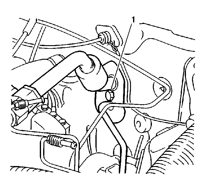
- Remove the A/C evaporative line extension bolt (1).
- Siphon the power steering fluid from the reservoir to prevent excessive spillage.
- Remove the power steering fluid reservoir bracket bolt.
- Remove the power steering fluid reservoir.
- Siphon the brake fluid from the reservoir to minimize spillage.
- Remove the brake booster vacuum connection from the intake plenum.
- Remove the brake pipes from the master cylinder.
- Remove the electrical connector from the master cylinder reservoir cap.
- Remove the sound insulator tabs.
- Remove the sound insulator.
- Match-mark the lower steering coupler with splines on the steering gear, if the same gear is to be reinstalled.
- Do not allow the steering wheel to rotate when the steering gear coupler is disconnected or damage to the SIR coil inside the steering column will result.
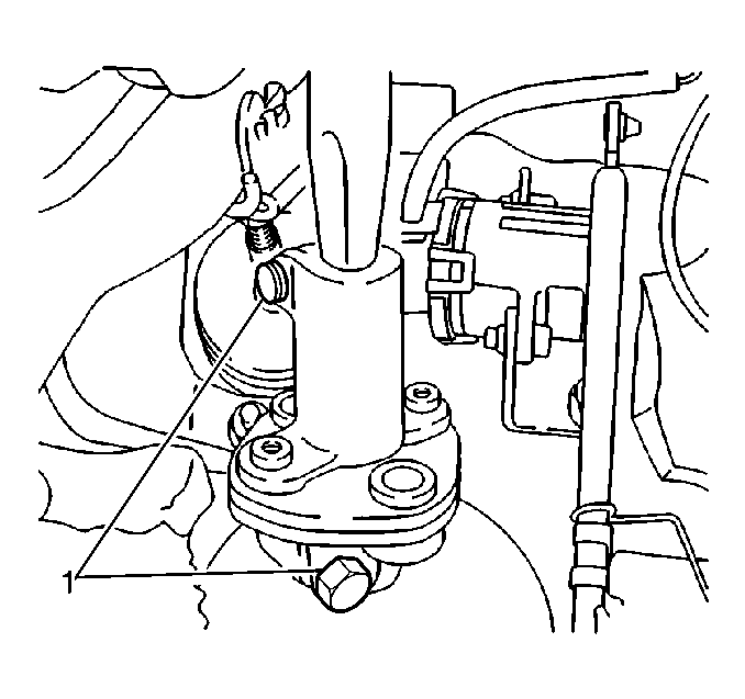
- Remove the steering coupler bolts (1) from the coupler.
- Perform the following steps to remove the steering column from the steering gear:
- Perform the following steps to remove the brake pedal from the brake power booster link rod:
- Remove the I/P driver knee bolster energy absorber.
- Remove the fuse.
- Remove the relay panel screws.
- Position the panels out of the way to enable easier access to the upper brake vacuum booster nuts.
- Remove the vacuum booster nuts from the inward side of cowl.
- Remove the vacuum booster with the master cylinder attached.
- Remove the A/C evaporator line extension quick connect.
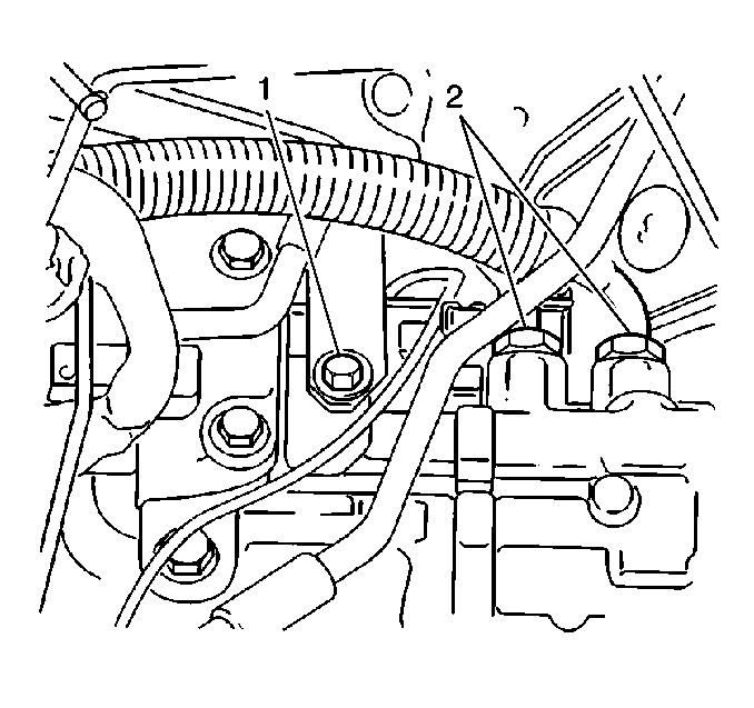
- Remove the power steering hoses (2) from the steering gear. The repositioning of the power steering hoses aids in the EBTCM/BPMV assembly removal.
- Remove the Electronic Brake Traction Control Module (EBTCM) assembly. Refer to Electronic Brake and Traction Control Module Replacement in ABS Brakes.
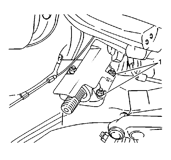
- Remove the heat shield upper fastening bolt (1).
- Raise and support the vehicle. Refer to Lifting and Jacking the Vehicle in General Information.
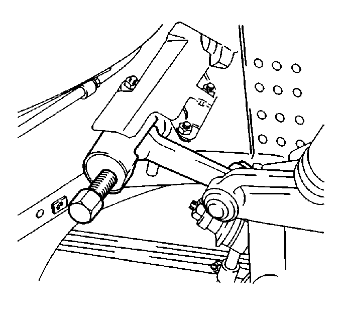
- Remove the pitman arm nut and washer. Mark alignment of the pitman arm in relation to the splines on the steering gear if the steering gear is to be reused.
- Use a universal pitman arm puller to remove the pitman arm. Note the rubber steering gear shaft protector.
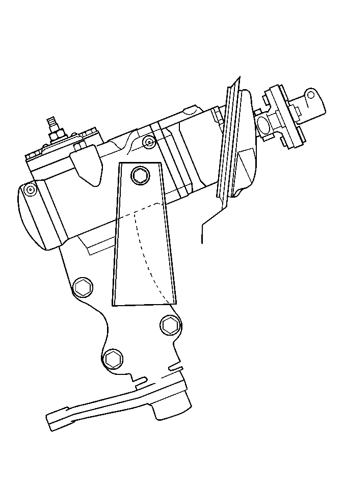
- Remove the lower the heat shield nuts (1).
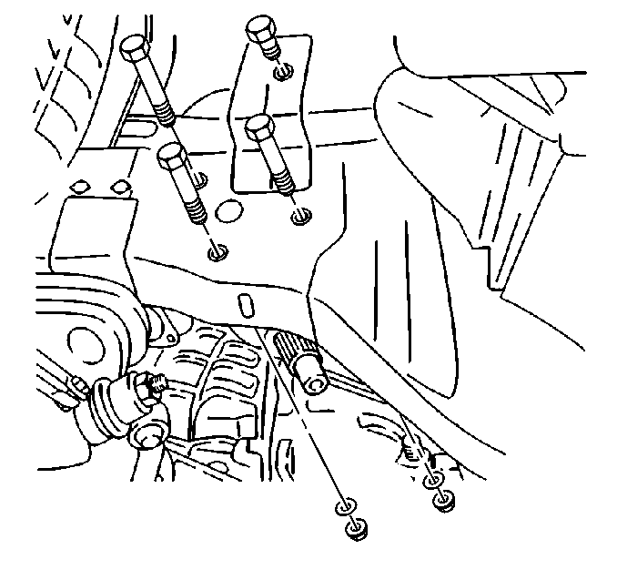
- Remove the steering gear lower bolts, nuts, and washers.
- Lower the vehicle.
- Remove the heat shield.
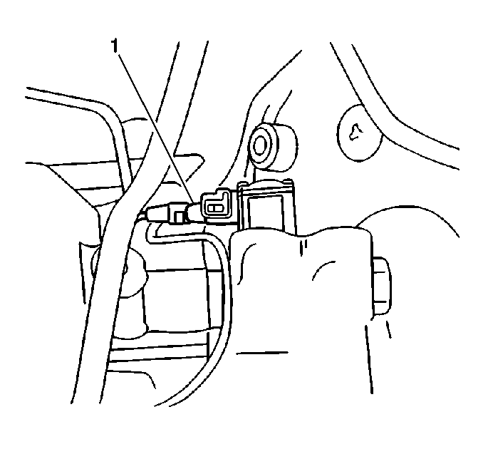
- Remove the electrical connection (1) from the power steering fluid flow control valve actuator.
- Remove the upper steering gear bolt and shim(s). Note the position of the shim(s) for reinstallation.
- Remove the steering gear.
Caution: Unless directed otherwise, the ignition and start switch must be in the OFF or LOCK position, and all electrical loads must be OFF before servicing any electrical component. Disconnect the negative battery cable to prevent an electrical spark should a tool or equipment come in contact with an exposed electrical terminal. Failure to follow these precautions may result in personal injury and/or damage to the vehicle or its components.
Important: After the key is removed, a substantial range of steering wheel travel is possible before the locking mechanism will set, therefore, it is necessary to lock the steering wheel with a locking device.
| 21.1. | Place the steering wheel in the straight ahead position. |
| 21.2. | Lock the steering wheel in place with the appropriate device. |
| 21.3. | Remove the key from the ignition. |
| 21.4. | Carefully spread the clamp open to allow the shaft to be moved upward and out of the way of the steering gear connection. |
| 22.1. | Remove the retaining clip from the pin. |
| 22.2. | Drive the pin out of the linkage rod. |
Installation Procedure
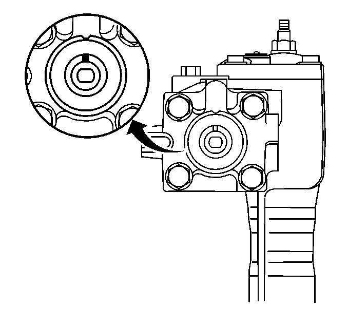
- Rotate the stub shaft from stop to stop with an 8 mm (5/16 in) open-end wrench counting the number of turns before installing on the vehicle.
- Starting at either stop, turn the stub shaft back 1/2 the total number of turns.
- Align the mark on the stub shaft to V mark on the steering gear case. This is the center of the gear.
- Install steering gear.
- Install the shim(s).
- Install the upper steering gear bolt.
- Install the electrical connection (1) to the power steering fluid flow control valve actuator.
- Install the heat shield.
- Secure the heat shield with the upper heat shield bolt.
- Raise and support the vehicle. Refer to Lifting and Jacking the Vehicle in General Information.
- Install the lower steering gear bolts, nuts, and washers.
- Install the lower heat shield nuts (1).
- Perform the following steps to install the pitman arm:
- Install the pitman arm wash and nut.
- Lower the vehicle.
- Install the EBTCM assembly. Refer to Electronic Brake and Traction Control Module Replacement in ABS Brakes.
- Install the power steering gear inlet and outlet hoses to the steering gear.
- Use new O--rings when installing the A/C evaporator line extension quick connect.
- Lubricate the new O--rings with mineral oil 525 viscosity.
- Install the A/C evaporator line extension quick connect.
- Install the vacuum booster with master cylinder attached.
- Install the vacuum booster nuts to the inward side of cowl.
- Reposition the fuse and the relay panels.
- Tighten the screws until snug.
- Install the I/P driver knee bolster energy absorber.
- Perform the following steps to install the brake pedal to the brake power booster link rod:
- Position the lower steering coupler marks.
- Connect the coupler, if installing the same gear. If the gear has been replace, place the front wheels in the straight ahead position and connect the coupler.
- Install the coupler bolts (1) to the coupler.
- Install the sound insulator.
- Install the sound insulator tabs.
- Install the brake pipes to the master cylinder.
- Install the electrical connector to the master cylinder reservoir cap.
- Install the brake booster vacuum connection to intake plenum.
- Position the power steering fluid reservoir.
- Install the power steering fluid reservoir clamp bolt.
- Use new sealing O--rings when installing the A/C evaporator line extension to cowl.
- Lubricate the new O--rings with mineral oil, 525 viscosity.
- Install the A/C evaporator line extension to cowl.
- Install the upper radiator hose.
- Install the ECM to the electrical box.
- Install the three body harness electrical connectors (1).
- Install the windshield wiper assembly. Refer to Windshield Wiper Transmission Replacement in Wiper/Washer System.
- Fill the engine cooling system. Refer to Cooling System Draining and Filling in Engine Cooling.
- Fill the power steering system. Refer to Checking and Adding Power Steering Fluid .
- Bleed the power steering system. Refer to Power Steering System Bleeding .
- Recharge and leak check the A/C system. Refer to Refrigerant Recovery and Recharging in HVAC.
- Reconnect the negative battery cable.
- Reprogram applicable accessories. Refer to Reprogramming Accessories After Battery Disconnect in Engine Electrical.
Notice: Use the correct fastener in the correct location. Replacement fasteners must be the correct part number for that application. Fasteners requiring replacement or fasteners requiring the use of thread locking compound or sealant are identified in the service procedure. Do not use paints, lubricants, or corrosion inhibitors on fasteners or fastener joint surfaces unless specified. These coatings affect fastener torque and joint clamping force and may damage the fastener. Use the correct tightening sequence and specifications when installing fasteners in order to avoid damage to parts and systems.
Tighten
Tighten the upper steering gear bolt until snug. Tighten to final specifications
will be done after the remaining bolts are installed.

Tighten
Tighten the upper heat shield bolt to 8 N·m (71 lb in).

Tighten
Tighten the upper and the lower steering gear bolts to 40 N·m
(30 lb ft).

Tighten
Tighten the lower heat shield nuts to 15 N·m (11 lb ft).

| 13.1. | Ensure the rubber steering gear shaft protector is in place prior to installing the pitman arm. |
| 13.2. | Align the pitman arm with the marks on the steering gear if the until has not been replace. |
| 13.3. | The pitman arm and the steering gear are blind splined to assist in proper installation. |
Tighten
Tighten the pitman arm nut to 160 N·m (118 lb ft).
Tighten
Tighten the power steering gear inlet and outlet hoses to 28 N·m
(21 lb ft).
Tighten
Tighten the vacuum booster nuts to 20 N·m (15 lb ft).
| 26.1. | Drive the pin into the linkage rod. |
| 26.2. | Install the retaining clip to the pin. |

Tighten
Tighten the coupler bolts to 22 N·m (16 lb ft).
Tighten
Tighten the brake pipes to the master cylinder to 16 N·m
(12 lb ft).
Tighten
Tighten the power steering fluid reservoir clamp bolt to 7 N·m
(62 lb in).

Tighten
Tighten the A/C evaporator line extension bolt (1) to 20 N·m
(15 lb ft).

