| • |

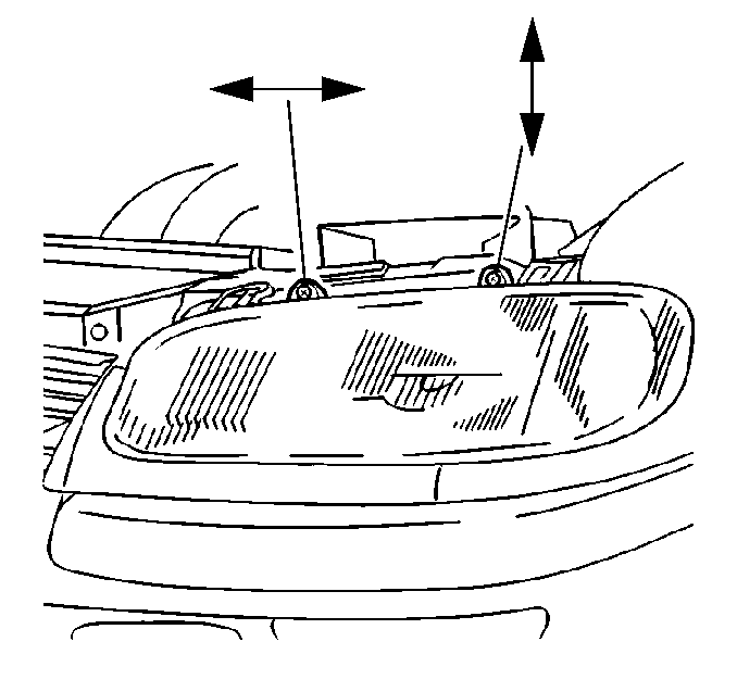
An adjusting screw on
the upper inboard side of the headlamp is available for horizontal headlamp
aim adjustment. |
| • |

The horizontal aim is
preset at the factory. The horizontal aim generally will not require adjustment. |
| • | Use the screen method to adjust the horizontal aim. Refer to Headlight
Aiming. |
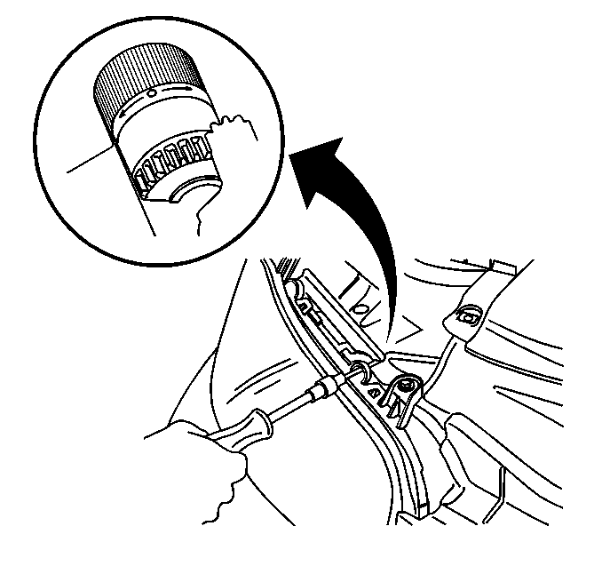
| • | A knob located on the back of the headlamp provides a point of
reference when adjusting to the left or to the right. This reference knob
will not determine the degree of aim. Do not use the reference knob to set
the headlamp aim. |
| • |

An adjusting screw on
the upper outboard side of the headlamp is available to set the vertical headlamp
aim. |
| • |

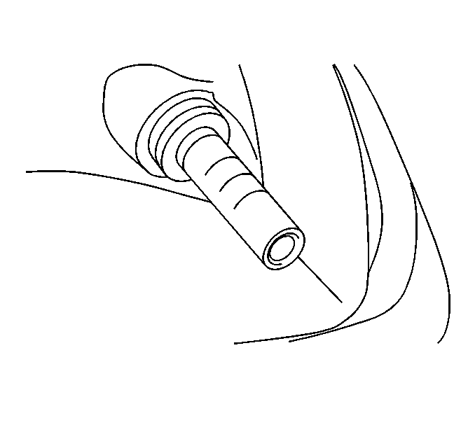
Use the integrated adjustment
bubble or use the screen method to set the vertical aim. Refer to Headlight
Aiming.Adjust the bubble until the bubble is in the middle of the 0 (zero)
on the level to set the vertical aim with the integrated bubble.
|
Visual Aiming Equipment
Do not use visual aiming equipment that attaches to the headlamp. Heat
from the headlamp may distort the plastic lens with the equipment attached.
The results of the visual aiming equipment must be equivalent to the
results of the screen method. Refer to Headlight Aiming.
Ensure the visual aiming equipment is in proper working order. Ensure
to use the visual aiming equipment in accordance with the manufacturer instructions.
Use a visual screen for beam pattern projection if using visual aiming
equipment with a photoelectric cell(s). Ensure the following conditions are
present:
| • | Ensure the vehicle is on a level surface parked 7.6 m (25 ft)
from the screen. |
| • | Ensure the pattern is proportional to its appearance. |
| • | Ensure the screen is plainly visible to the operator. |
| • | Ensure a horizontal reference line is present to allow for visual
appraisal of the headlamp beam. |
| • | Ensure a vertical reference line is present to allow for visual
appraisal of the headlamp beam. |
Headlamp Aiming By Screen Method
Ensure the following conditions are present:
| • | Ensure the area is large enough to accommodate the vehicle plus
an additional 7.6 m (25 ft) measured from the face of the headlamps
to the front of the visual screen. |
| • | Ensure the area is a darkened location. |
| • | Ensure floor on which the vehicle rests is flat with the bottom
of the screen. Make the necessary compensation if the floor is not level. |
| • | Ensure the aiming screen is 1.5 m x 3.7 m
(5 ft x 12 ft). The screen may consist of a vertical
wall with a clear uninterrupted area measuring 1.5 m x 3.7 m
(5 ft x 12 ft) if a regular commercial aiming
screen is not available. Ensure the wall is finished with a washable non-gloss
white paint. |
| • | Ensure the aiming screen is a matte-white surface. |
| • | Ensure the aiming screen is well shaded from the outside light. |
| | Important: The horizontal line or tape on the screen must be adjusted for each
vehicle checked. Vehicles of the same model and year will have different standing
height for the headlamps.
|
| • | Ensure the aiming screen is equipped with the following: |
| - | A vertical center line. |
| - | Two laterally adjustable vertical tapes. |
| - | A vertically adjustable horizontal tape. |
| • | Ensure provisions are made for moving the screen so that the screen
can align parallel with the rear axle. This allows for a horizontal line drawn
perpendicular from the center line of the screen to pass through the center
point between the two headlamps. |
| • | Ensure to paint a reference line on the floor to identify the
proper location of the headlamps, when they are being aimed, once the screen
is set in a permanent location. |
Perform the following steps to prepare the vehicle for checking the
beam aim:
- Completely assemble all the components on the vehicle.
- Ensure the vehicle is at it's normal operating weight. This includes
the spare tire, tools, and any other items normally carried. Additionally,
ensure the vehicle fuel load is no less than 1/2 tank.
- Check the vehicle tires for correct pressure.
- Turn the ignition switch to the ON position.
- Activate the Automatic Level Control (ALC) system.
- Position the vehicle in the following position:
| • | So it is square with the aiming screen. |
| • | So the headlamps are directly over the painted reference line
on the floor. |
- Sight through the center of the rear window and over the hood
to locate the vertical line on the aiming screen so that it is in line with
the center of the vehicle.
- Mark the center of the front window and the center of the rear
window with narrow tape to create sights. Use these sights to locate the center
of the vehicle.
- Move the vehicle or move the screen until the center line of the
screen comes into alignment with these two points.
- Close the doors.
- Rock the vehicle sideways to stabilize the suspension.
- Switch the headlamps on to low beam.
- Observe the left edge and top edge of the high intensity zone
on the screen.
- Use the inboard adjusting screw to adjust the horizontal aim if
the left edge is more than the following measurements:
| • | More than 102 mm (4 in) RIGHT of straight ahead. |
| • | More than 102 mm (4 in) LEFT of straight ahead. |
- Use the outboard adjusting screw to adjust the vertical aim if
the top edge is more than the following measurements:
| • | More than 102 mm (4 in) ABOVE the horizontal line. |
| • | More than 102 mm (4 in) BELOW the horizontal line. |


