Removal Procedure
Tools Required
| • | J 42066 Rear Hub Holding Tool |
| • | J 6125-1B Slide Hammer |
| • | J 23129 Axle Boot Remover |
| • | J 36797-A Getrag Axle Output Shaft Seal Installer |
- Remove the transmission mount. Refer to Transmission Mount .
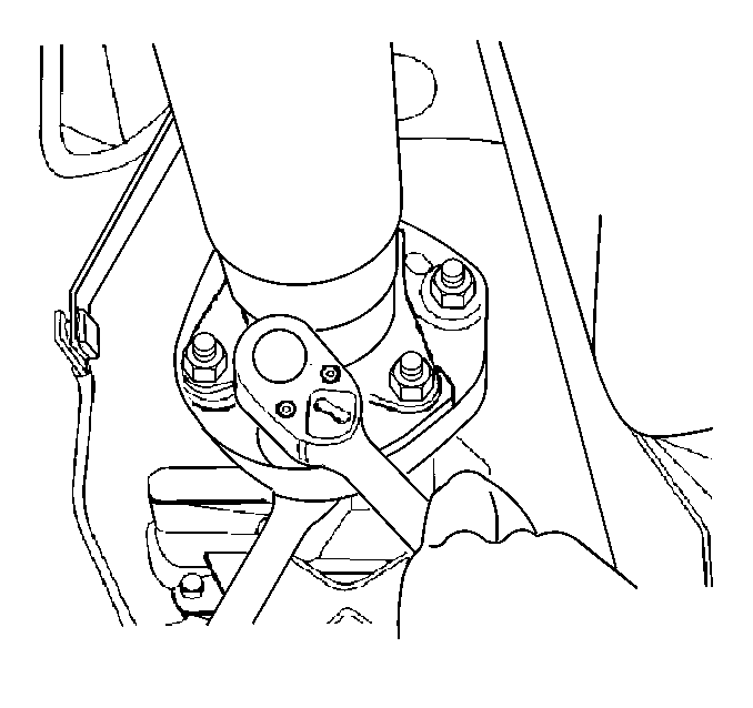
- Remove the propeller shaft coupling bolts.
- Remove the propeller shaft coupling from flange. Use a screwdriver to pry propeller shaft coupling away from flange.
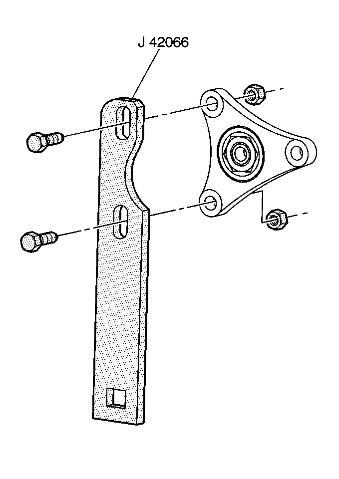
- Install the J 42066 onto the drive flange using nuts and bolts supplied with tool.
- While holding the J 42066 and using a 30 mm deepwell socket to remove the flange nut.
- Discard the nut.
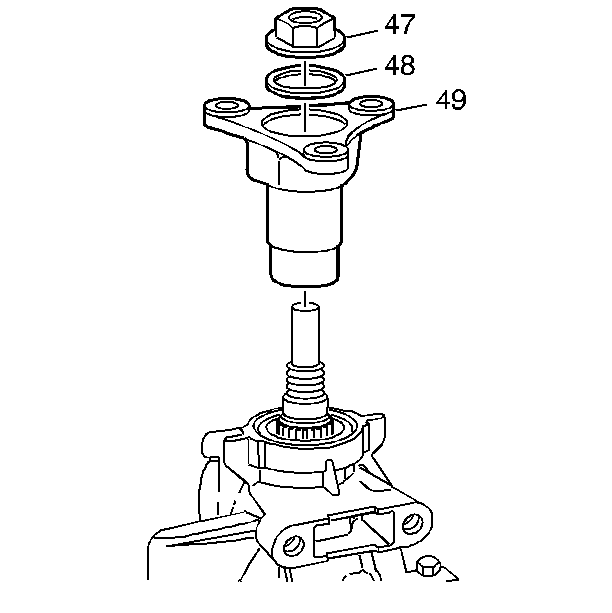
- Remove the drive flange (49) from transmission output shaft.
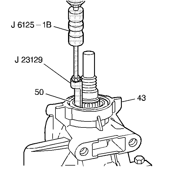
- Using the J 6125-1B and the J 23129 remove the case extension seal (50) from the transmission (43).
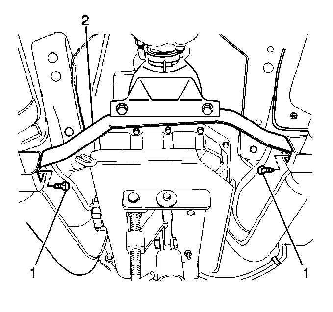
- Remove the catalytic converter support bracket bolts (1) and bracket.
- Disconnect the transmission speed sensor electrical connector.
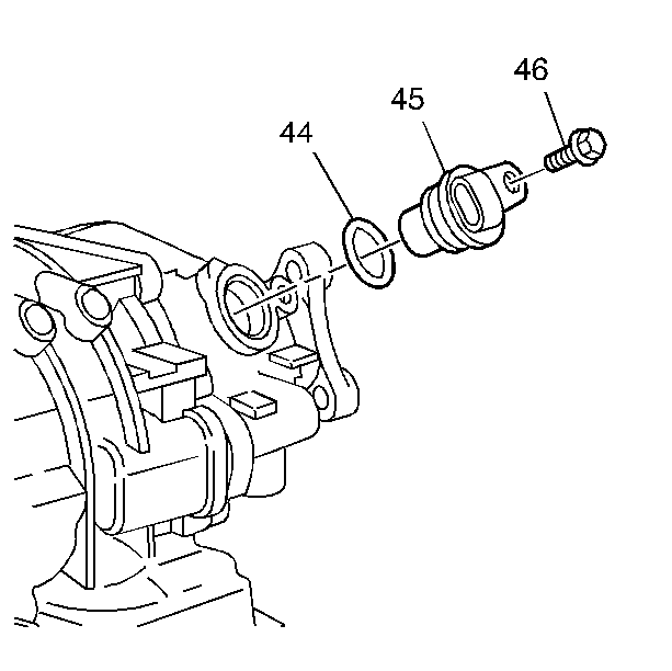
- Remove the transmission speed sensor bolt and sensor with seal. Use hand pressure to twist sensor while pulling outward. Do not pry on sensor.
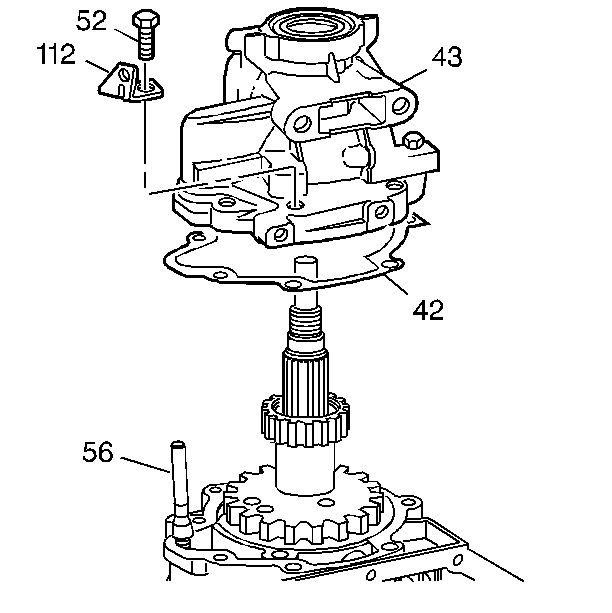
- Remove rear oxygen sensor harness clips (112) from the case extension.
- Remove the case extension bolts (52).
- Remove the case extension (43).
- Remove the case extension gasket (42).
Installation Procedure
- Install the new case extension gasket (42).
- Install the case extension (43).
- Install the case extension bolts (52).
- Install the rear oxygen sensor harness clips (112) to the case extension.
- Install the transmission speed sensor seal (44), sensor (45) and the bolt (46).
- Connect the transmission speed sensor electrical connector.
- Install the catalytic converter support bracket bolts (1) and bracket.
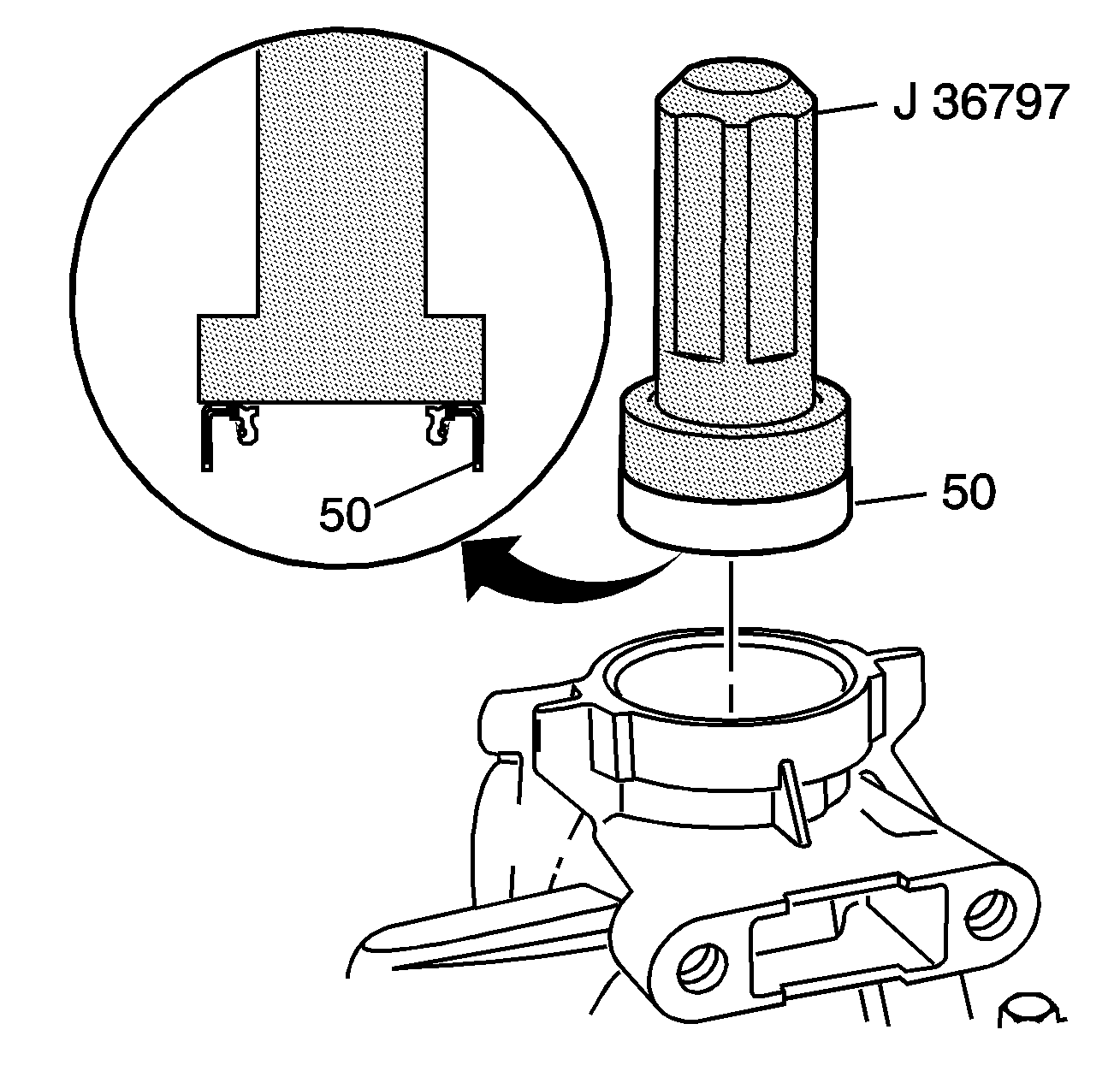
- Using the J 36797-A install the new seal (50) into the case extension.
- Install the drive shaft flange, washer, and the new nut onto the output shaft.
- Install the J 42066 onto the drive flange using nuts and bolts supplied with tool.
- While holding the J 42066 and using a 30 mm deepwell socket to tighten the flange nut.
- Install the propeller shaft coupling to drive flange.
- Install the propeller shaft coupling bolts.
- Install the transmission mount. Refer to Transmission Mount .
- Inspect and adjust the transmission fluid level. Refer to Transmission Fluid Check .

Notice: Use the correct fastener in the correct location. Replacement fasteners must be the correct part number for that application. Fasteners requiring replacement or fasteners requiring the use of thread locking compound or sealant are identified in the service procedure. Do not use paints, lubricants, or corrosion inhibitors on fasteners or fastener joint surfaces unless specified. These coatings affect fastener torque and joint clamping force and may damage the fastener. Use the correct tightening sequence and specifications when installing fasteners in order to avoid damage to parts and systems.
Tighten
Tighten the bolts to 32 N·m (23 lb ft).

Tighten
Tighten the speed sensor bolt to 9 N·m (78 lb in).



Notice: Use the correct fastener in the correct location. Replacement fasteners must be the correct part number for that application. Fasteners requiring replacement or fasteners requiring the use of thread locking compound or sealant are identified in the service procedure. Do not use paints, lubricants, or corrosion inhibitors on fasteners or fastener joint surfaces unless specified. These coatings affect fastener torque and joint clamping force and may damage the fastener. Use the correct tightening sequence and specifications when installing fasteners in order to avoid damage to parts and systems.
Tighten
Tighten the drive flange nut to 100 N·m (74 lb ft).

Tighten
Tighten the propeller shaft coupling bolts to 95 N·m (70 lb ft).
