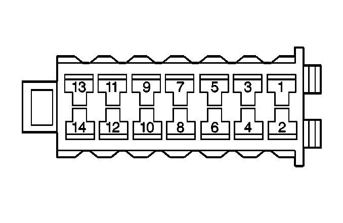
| |||||||||
|---|---|---|---|---|---|---|---|---|---|
Connector Part Information |
| ||||||||
Pin | Wire Color | Circuit No. | Function | ||||||
1 | BLK/RED BRN/PPL | FA811 XY804 | Fuel Door Release Input Signal from the Body Control Module and Trunk Release Button | ||||||
2 | BLK/RED | FA809 | Unlock Door Output Signal to Driver's Door Actuator | ||||||
3 | -- | -- | Not Used | ||||||
4 | BRN/PPL | XY803 | Driver's Door Unlock Signal from the Body Control Module | ||||||
5 | RED | A888 | Battery Power Input | ||||||
6 | BLK/RED | FA805 | Fuel Door Unlock Signal to the Fuel Lid Actuator | ||||||
7 | BRN/PPL | XY807 | Doors Unlock Input Signal from the Body Control Module | ||||||
8 | RED | A911 | Ignition Power Input | ||||||
9 | BLK/RED BRN/PPL | FA812 XY805 | Trunk Lid Lock Release Input Signal from the Body Control Module and Fuel Lid Unlock Button | ||||||
10 | BLK/RED | FA801 | Unlock Door Output Signal to Passenger and Rear Door Actuators | ||||||
11 | BRN/PPL | XY806 | Doors Lock Input Signal from Body Control Module | ||||||
12 | BLK/YEL | FB801 | Doors Lock Output Signal to All Doors and Fuel Lid | ||||||
13 | BLK/RED | FA807 | Trunk Lid Lock Output Signal to the Trunk Lid Actuator | ||||||
14 | BLK | F911 | Ground | ||||||
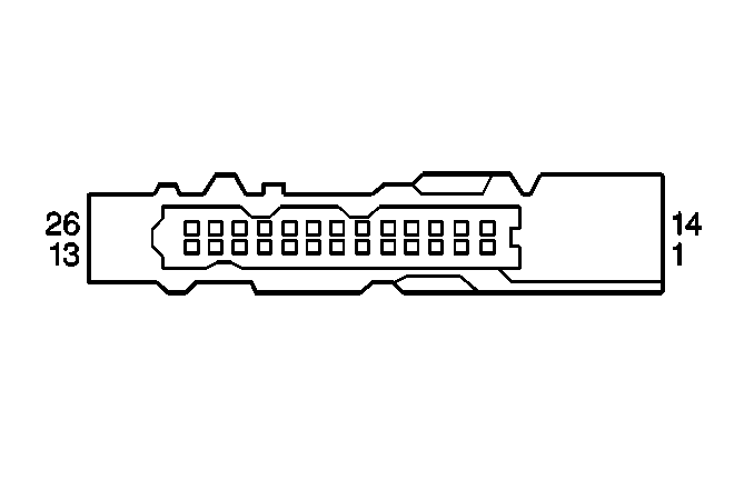
| ||||||||||
|---|---|---|---|---|---|---|---|---|---|---|
Connector Part Information |
| |||||||||
Pin | Wire Color | Circuit No. | Function | Component Connector Cavity | DTC(s) Affected | Possible Symptoms From a Faulty Cirtuit | ||||
1-3 | Not Used | |||||||||
4 | BLK/BRN | FX75 | Memory Pot Signal | 18, 19 and 20 | All Memory Mirrors Become Disabled | |||||
5 | BRN | X75 | Memory Pot Signal | 18, 19 and 20 | All Memory Mirrors Become Disabled | |||||
6 | GRY/GRN | RU60 | Memory Pot Signal | 20 | RH Outside Memory Mirror Becomes Disabled | |||||
7 | GRY | R70 | Memory Pot Signal | 20 | RH Outside Memory Mirror Becomes Disabled | |||||
8 | GRY/BLK | RF60 | Memory Pot Signal | 19 | Inside Memory Mirror Becomes Disabled | |||||
9 | GRY/YEL | RB60 | Memory Pot Signal | 19 | Inside Memory Mirror Becomes Disabled | |||||
10 | GRY/GRN | RU50 | Memory Pot Signal | 18 | LH Outside Memory Mirror Becomes Disabled | |||||
11 | GRY | R60 | Memory Pot Signal | 18 | LH Outside Memory Mirror Becomes Disabled | |||||
12 | Not Used | |||||||||
13 | BLK/RED | FA75 | Memory Mirror Common | |||||||
14-20 | Not Used | |||||||||
21 | GRN | U80 | LH Mirror Control Signal | |||||||
22 | YEL | B12 | LH Mirror Control Signal | |||||||
23 | BLU/WHT | PM60 | Inside Mirror Control Signal | |||||||
24 | BLU/RED | PA60 | Inside Mirror Control Signal | |||||||
25 | BLu | P70 | RH Mirror Control Signal | |||||||
26 | GRY | R65 | RH Mirror Control Signal | |||||||

| |||||||||
|---|---|---|---|---|---|---|---|---|---|
Connector Part Information |
| ||||||||
Pin | Wire Color | Circuit No. | Function | ||||||
1 | GRY/WHT | RM2 | Door Open Signal | ||||||
2 | GRY | R2 | Door Open Signal | ||||||
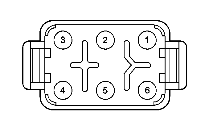
| |||||||
|---|---|---|---|---|---|---|---|
Connector Part Information |
| ||||||
Pin | Wire Color | Circuit No. | Function | ||||
1 | -- | -- | Not Used | ||||
2 | BLK/RED | FA809 | Door Unlock Signal | ||||
3-5 | -- | -- | Not Used | ||||
6 | BLK/YEL | FB9 | Door Lock Signal | ||||
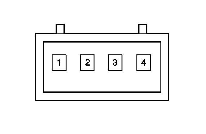
| |||||||
|---|---|---|---|---|---|---|---|
Connector Part Information |
| ||||||
Pin | Wire Color | Circuit No. | Function | ||||
1 | BLK/BRN | FX805 | Door Lock Signal | ||||
2 | BLK/PPL | FY805 | Door Unlock Signal | ||||
3 | RED/BLU | AP807 | Illumination Signal | ||||
4 | BLK | F12 | Ground to G200 | ||||

| |||||||
|---|---|---|---|---|---|---|---|
Connector Part Information |
| ||||||
Pin | Wire Color | Circuit No. | Function | ||||
1 | RED | A2 | B+ from Fuse #1 | ||||
2 | GRY/GRN | RU6 | Window Up Signal | ||||
3 | BLU/RED | PA2 | Window Down Signal | ||||
4 | BLK | F11 | Ground to G200 | ||||
5 | YEL | B11 | B+ Input, Power Window Regulator Enable Signal | ||||
6 | -- | -- | Not Used | ||||
| |||||||
|---|---|---|---|---|---|---|---|
Connector Part Information |
| ||||||
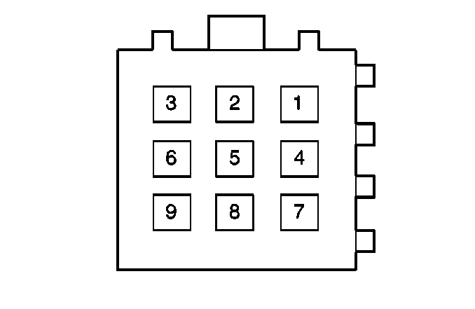
Pin | Wire Color | Circuit No. | Function | ||||
1 | BLU/RED | PA2 | LH Front Door Window Motor Control | ||||
2 | GRY/GRN | RU5 | LH Front Door Window Motor Control | ||||
3 | BLU/RED | PA3 | LH Rear Door Window Motor Control | ||||
4 | GRY/GRN | RU15 | LH Rear Door Window Motor Control | ||||
5 | WHT | M5 | Rear Window Switch Voltage | ||||
6 | BRN | X2 | B+ from Fuse #15 | ||||
7 | RED | A3 | B+ from Fuse #1 | ||||
8 | -- | -- | Not Used | ||||
9 | GRY | R10 | All Door Jamb Signal | ||||

| |||||||
|---|---|---|---|---|---|---|---|
Connector Part Information |
| ||||||
Pin | Wire Color | Circuit No. | Function | ||||
1 | YEL | B20 | Motor Control | ||||
2 | GRN | U200 | Motor Control | ||||
3 | BLK/RED | FA81 | Motor Common | ||||
4 | BRN | X60 | Memory Pot Signal | ||||
5 | BLK/BRN | FX60 | Memory Pot Signal | ||||
6 | GRY | R60 | Memory Pot Signal | ||||
7 | GRY/GRN | RU60 | Memory Pot Signal | ||||
8 | BLK/WHT | FM15 | Defogger On Signal | ||||
9 | BLK | F50 | Ground to G200 | ||||

| |||||||
|---|---|---|---|---|---|---|---|
Connector Part Information |
| ||||||
Pin | Wire Color | Circuit No. | Function | ||||
1 | YEL | B2 | Motor control | ||||
2 | GRN | U1 | Motor Control | ||||
3 | BLK/RED | FA4 | Motor Common | ||||
4-7 | -- | -- | Not Used | ||||
8 | BLK/WHT | FM2 | Defogger On Signal | ||||
9 | BLK | F2 | Ground to G200 | ||||

| |||||||
|---|---|---|---|---|---|---|---|
Connector Part Information |
| ||||||
Pin | Wire Color | Circuit No. | Function | ||||
1 | -- | -- | Not used | ||||
2 | BLK/RED | FA804 | Door Lock Signal | ||||
3-5 | -- | -- | Not Used | ||||
6 | BLK/YEL | FB805 | Door Unlock Signal | ||||

| |||||||
|---|---|---|---|---|---|---|---|
Connector Part Information |
| ||||||
Pin | Wire Color | Circuit No. | Function | ||||
1 | RED | A1 | B+ from Fuse #7 | ||||
2 | GRY/GRN | RU2 | Window Up Signal | ||||
3 | BLU/RED | PA2 | Window Down Signal | ||||
4 | BLK | F1 | Ground to G200 | ||||
5 | YEL | B1 | B+ Input, Power Window Regulator Enable Signal | ||||
6 | Not Used | ||||||
| |||||||
|---|---|---|---|---|---|---|---|
Connector Part Information |
| ||||||
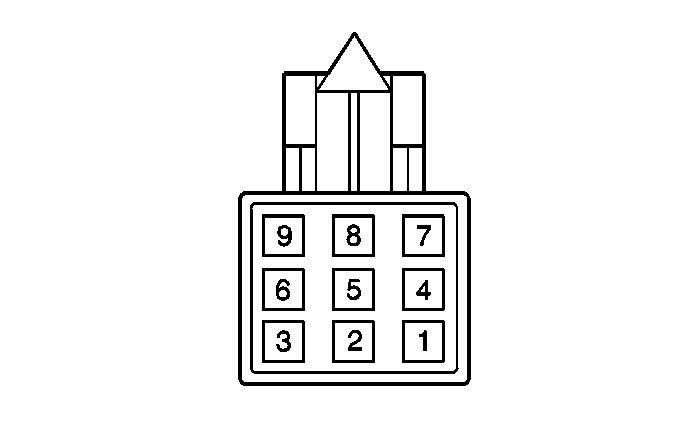
Pin | Wire Color | Circuit No. | Function | ||||
1 | GRY/GRN | RU1 | Window Up Signal | ||||
2 | -- | -- | Not Used | ||||
3 | BLK | F2 | Ground to G200 | ||||
4-6 | -- | -- | Not Used | ||||
7 | WHT | M1 | Power from Main Switch | ||||
8 | -- | -- | Not Used | ||||
9 | BLU/RED | PA1 | Window Down Signal | ||||
| |||||||
|---|---|---|---|---|---|---|---|
Connector Part Information |
| ||||||
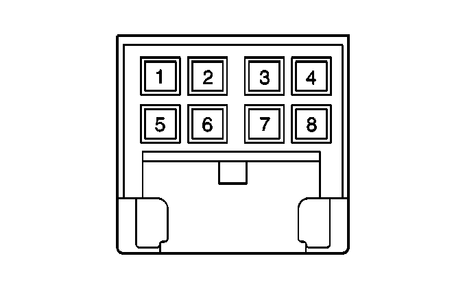
Pin | Wire Color | Circuit No. | Function | ||||
1 | BRN | X10 | Fused Battery Voltage | ||||
2 | BLK | F5 | Ground to G200 | ||||
3 | GRY | R11 | RH Mirror Control | ||||
4 | GRN | U1 U10 | LH Mirror Control | ||||
5 | BLK/RED | FA2 | Mirror Common | ||||
6 | -- | -- | Not Used | ||||
7 | YEL | B2 B10 | LH Mirror Control | ||||
8 | BLU | P3 | RH Mirror Control | ||||

| |||||||
|---|---|---|---|---|---|---|---|
Connector Part Information |
| ||||||
Pin | Wire Color | Circuit No. | Function | ||||
1 | -- | -- | Not Used | ||||
2 | BLK/RED | FA809 | Door Lock Signal | ||||
3-5 | -- | -- | Not Used | ||||
6 | BLK/YEL | FB9 | Door Lock Signal | ||||

| |||||||
|---|---|---|---|---|---|---|---|
Connector Part Information |
| ||||||
Pin | Wire Color | Circuit No. | Function | ||||
1 | BLK/BRN | FX805 | Door Lock Signal | ||||
2 | BLK/PPL | FY805 | Door Unlock Signal | ||||
3 | RED/BLU | AP807 | Illumination Signal | ||||
4 | BLK | F12 | Ground to G200 | ||||

| |||||||
|---|---|---|---|---|---|---|---|
Connector Part Information |
| ||||||
Pin | Wire Color | Circuit No. | Function | ||||
1 | RED | A2 | B+ from Fuse #1 | ||||
2 | GRY/GRN | RU6 | Window Up Signal | ||||
3 | BLU/RED | PA2 | Window Down Signal | ||||
4 | BLK | F11 | Ground to G200 | ||||
5 | YEL | B2 | B+ Input, Power Window Regulator Enable Signal | ||||
6 | -- | -- | Not Used | ||||
| |||||||
|---|---|---|---|---|---|---|---|
Connector Part Information |
| ||||||
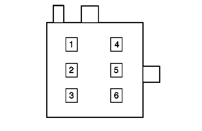
Pin | Wire Color | Circuit No. | Function | ||||
1 | BLU/RED | PA1 | RH Front Side Door Window Control | ||||
2 | GRY/GRN | RU6 | RH Front Side Door Window Control | ||||
3 | BLU/RED | PA4 | RH Rear Side Door Window Control | ||||
4 | GRY/GRN | RU16 | RH Rear Side Door Window Control | ||||
5 | BLK | F22 | Ground to G200 | ||||
6 | YEL | B9 | B+ Voltage Feed | ||||

| |||||||
|---|---|---|---|---|---|---|---|
Connector Part Information |
| ||||||
Pin | Wire Color | Circuit No. | Function | ||||
1 | GRY | R5 | Motor Control | ||||
2 | BLU | P10 | Motor Control | ||||
3 | BLK/RED | FA65 | Motor Common | ||||
4 | BRN | X65 | Memory Pot Signal | ||||
5 | BLK/BRN | FX65 | Memory Pot Signal | ||||
6 | GRY | R70 | Memory Pot Signal | ||||
7 | GRY/GRN | RU60 | Memory Pot Signal | ||||
8 | BLK/WHT | FM20 | Defogger On Signal | ||||
9 | BLK | F55 | Ground to G200 | ||||

| |||||||
|---|---|---|---|---|---|---|---|
Connector Part Information |
| ||||||
Pin | Wire Color | Circuit No. | Function | ||||
1 | GRY | R4 | Motor Control | ||||
2 | BLU | P2 | Motor Control | ||||
3 | BLK/RED | FA4 | Motor Common | ||||
4-7 | -- | -- | Not Used | ||||
8 | BLK/WHT | FM2 | Defogger On Signal | ||||
9 | BLK | F2 | Ground to G200 | ||||

| |||||||
|---|---|---|---|---|---|---|---|
Connector Part Information |
| ||||||
Pin | Wire Color | Circuit No. | Function | ||||
1 | -- | -- | Not Used | ||||
2 | BLK/RED | FA804 | Door Lock Signal | ||||
3-5 | -- | -- | Not Used | ||||
6 | BLK/YEL | FB805 | Door Unlock Signal | ||||

| |||||||
|---|---|---|---|---|---|---|---|
Connector Part Information |
| ||||||
Pin | Wire Color | Circuit No. | Function | ||||
1 | RED | A1 | B+ from Fuse #7 | ||||
2 | GRY/GRN | RU2 | Window Up Signal | ||||
3 | BLU/RED | PA2 | Window Down Signal | ||||
4 | BLK | F1 | Ground to G200 | ||||
5 | YEL | B1 | B+ Input, Power Window Regulator Enable Signal | ||||
6 | Not Used | ||||||

| |||||||
|---|---|---|---|---|---|---|---|
Connector Part Information |
| ||||||
Pin | Wire Color | Circuit No. | Function | ||||
1 | GRY/GRN | RU1 | Window Up Signal | ||||
2 | -- | -- | Not Used | ||||
3 | BLK | F2 | Ground to G200 | ||||
4-6 | -- | -- | Not Used | ||||
7 | WHT | M1 | Power from Main Switch | ||||
8 | -- | -- | Not Used | ||||
9 | BLU/RED | PA1 | Window Down Signal | ||||
| |||||||||
|---|---|---|---|---|---|---|---|---|---|
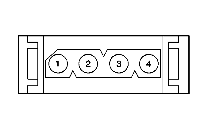
Connector Part Information |
| ||||||||
Pin | Wire Color | Circuit No. | Function | ||||||
1 | RED | A401 | B+ from Fuse #12 | ||||||
2 | BLK/YEL | FB101 | Brake Lamp ON Signal | ||||||
3 | BRN | X120 | Fused Battery Voltage | ||||||
4 | BLK/BRN | FX102 | BTSI Signal | ||||||
