For 1990-2009 cars only
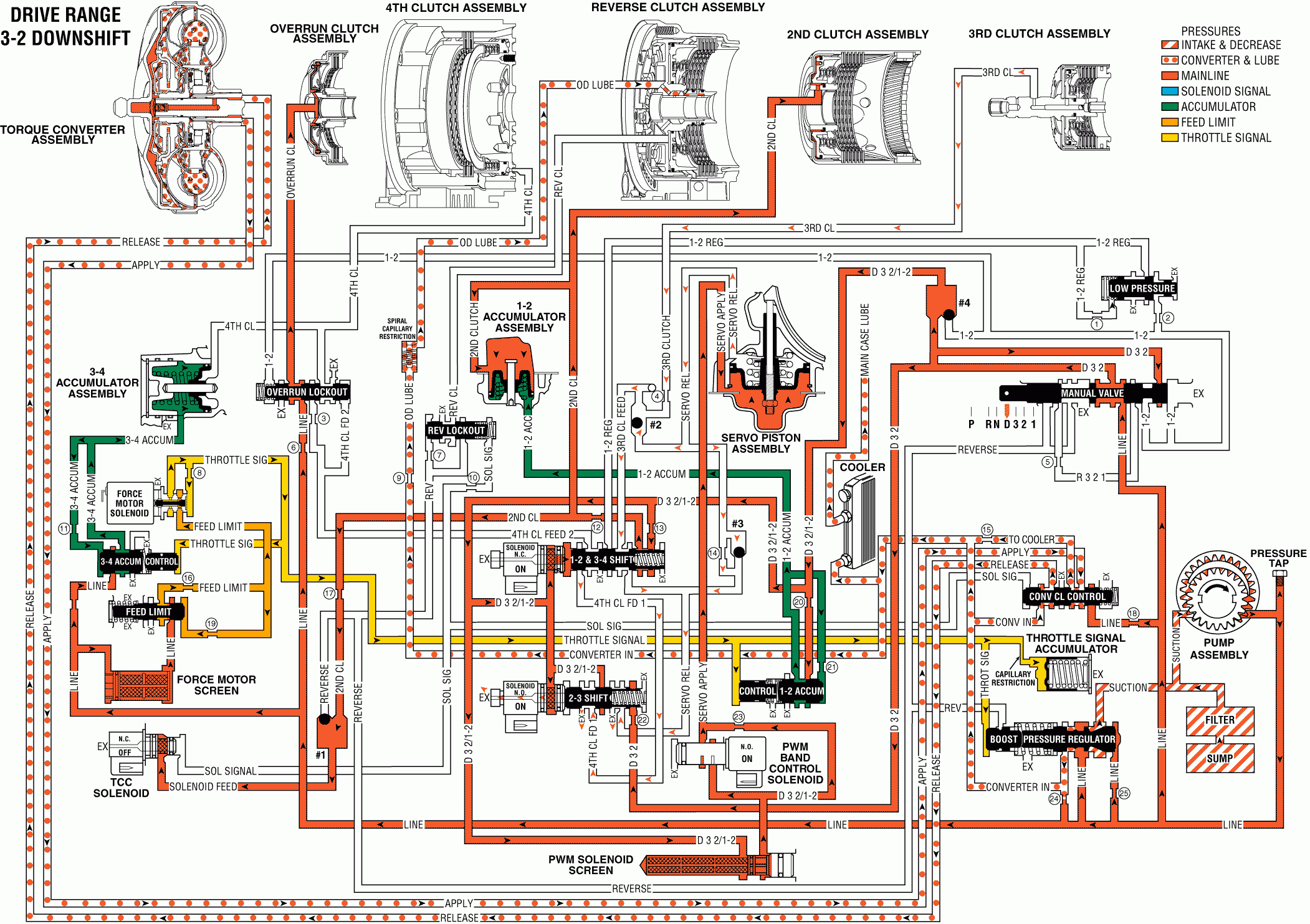
Similar to a 4-3 downshift, if the transmission is operating in Third gear a 3-2 downshift can occur due to coastdown, heavy throttle, or increased engine load conditions. A 3-2 downshift occurs when the TCM receives the appropriate input signals to energize (turn ON) the 2-3 shift solenoid. During the downshift the following changes occur:
2-3 Shift Solenoid: Energized by the TCM, the solenoid closes and blocks D32/1-2 fluid from acting on the end of the 2-3 shift valve. D32/1-2 fluid at the end of the valve is open to an exhaust passage through the solenoid.2-3 Shift Valve: Without D32/1-2 fluid pressure from the shift solenoid, spring force moves the valve into the First and Second gear position. In this position the following changes occur:
| • | D32/1-2 fluid at the middle of the valve is blocked from entering the 4th clutch feed 1 fluid circuit. |
| • | 4th clutch feed 1 fluid exhausts past the valve. |
| • | D32 fluid is blocked from entering the servo release fluid circuit. |
| • | Servo release fluid exhausts past the valve. Remember that in Third and Fourth gear servo release fluid fed the 3rd clutch fluid circuit. |
3rd Clutch Releases
3rd Clutch Piston: 3rd clutch fluid pressure exhausts from the piston, thereby releasing the 3rd clutch plates.Checkball #2: Exhausting 3rd clutch fluid is orificed (#24) to the 3rd clutch checkvalve, located in the main case valve body. This exhausting fluid keeps the ball unseated and flows through both the servo release and 3rd clutch feed fluid circuits.
Servo Piston: Servo release fluid pressure exhausts from the piston. Servo apply fluid pressure overcomes the force from both the servo cushion (99) and servo return (103) springs. This moves the servo piston and apply pin (102 to apply the brake band.
Checkball #3: Exhausting servo release fluid seats the ball and is forced through orifice #22d. This orifice helps control the exhaust of servo release fluid which helps control the 3rd clutch release rate. The orifice also helps control the apply rate of the brake band.
Brake Band Applies
Pulse Width Modulated (PWM) Band Apply Solenoid: The TCM controls the solenoid's duty cycle depending on vehicle application and operating conditions. The duty cycle determines the rate at which the solenoid regulates D32/1-2 fluid into the servo apply fluid circuit. Refer to the Electronic Components Section for a detailed description of the PWM solenoid operation.Converter Clutch
Torque Converter Clutch (TCC): The converter clutch releases prior to all downshifts. However, in Second gear the converter clutch will not re-apply under normal operating conditions. Refer to 4-3 Downshift for a complete explanation of the converter clutch hydraulic circuits during TCC release.3-2 Downshift - Valves in Second Gear Position

