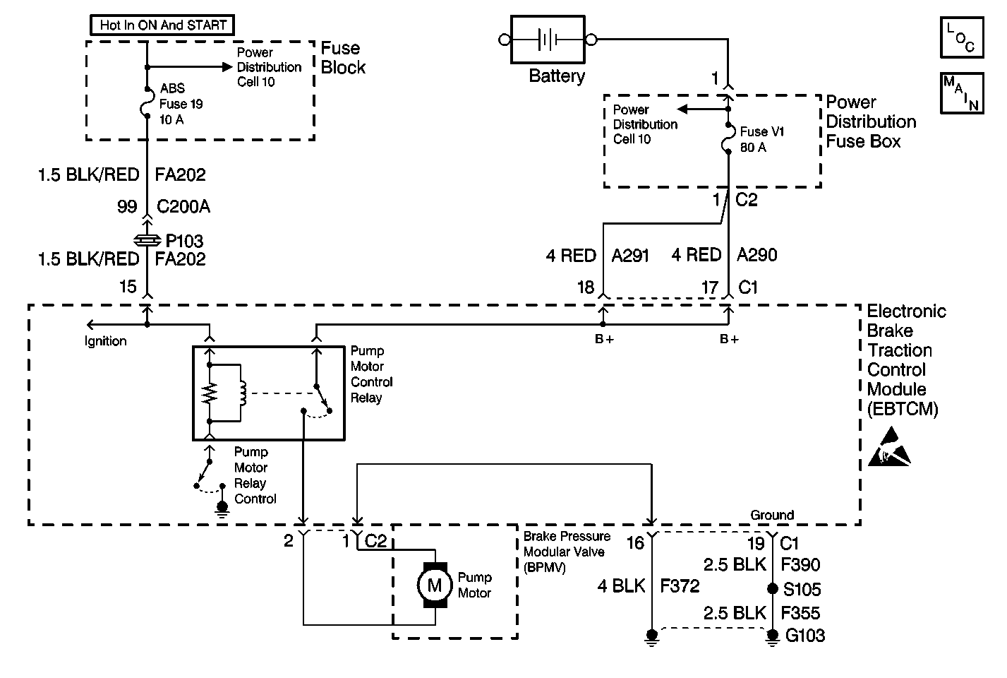
Circuit Description
The pump motor is an integral part of the BPMV, while the pump motor relay is integral to the EBTCM. The pump motor relay is not engaged during normal system operation. When ABS or TCS operation is required, the EBTCM activates the pump motor relay and battery power is provided to the pump motor.
Conditions for Setting the DTC
| • | Pump motor voltage is not present 60 milliseconds after activation of the pump motor relay. |
| • | Pump motor voltage is present for more than 2.5 seconds with no activation of the pump motor relay. |
| • | Pump motor voltage is not present for at least 40 milliseconds after the pump motor relay is commanded off. |
Action Taken When the DTC Sets
| • | A malfunction DTC stores. |
| • | The ABS/TCS disables. |
| • | The amber ABS/TCS indicator(s) turn on. |
Conditions for Clearing the DTC
| • | The condition responsible for setting the DTC no longer exists and the scan tool Clear DTCs function is used. |
| • | 100 ignition cycles pass with no DTC(s) detected. |
Diagnostic Aids
| • | It is very important that a thorough inspection of the wiring and connectors be performed. Failure to carefully and fully inspect wiring and connectors may result in misdiagnosis, causing part replacement with reappearance of the malfunction. |
| • | Thoroughly inspect any circuitry that may be causing the complaint for the following conditions: |
| - | Backed out terminals |
| - | Improper mating |
| - | Broken locks |
| - | Improperly formed or damaged terminals |
| - | Poor terminal-to-wiring connections |
| - | Physical damage to the wiring harness |
| • | The following conditions may cause an intermittent malfunction: |
| - | A poor connection |
| - | Rubbed-through wire insulation |
| - | A broken wire inside the insulation |
| • | If an intermittent malfunction exists refer to Intermittents and Poor Connections Diagnosis in Wiring Systems for further diagnosis. |
A disconnected pump motor connector will cause this malfunction.
Test Description
The numbers below refer to step numbers on the diagnostic table.
-
This step checks for a short to ground in CKTs A291 and A290.
-
This step checks for an open in CKTs A291 and A290.
-
This step checks for a mechanical malfunction with the pump motor or the pump. This step also cleans the commutator and brushes of the pump motor prior to the resistance check in step 15.
Step | Action | Value(s) | Yes | No |
|---|---|---|---|---|
1 | Was the Diagnostic System Check performed? | -- | ||
2 | Inspect the 80A Fuse V1 Maxifuse® , in the Power Distribution Fuse Box. Is the fuse OK? | -- | ||
3 |
Is the fuse OK? | -- | ||
Is the resistance within the range specified in the value(s) column? | OL (infinite) | |||
5 |
Is the fuse OK? | -- | ||
6 | Replace the BPMV. Refer to Brake Pressure Modulator Valve Replacement . Is the replacement complete? | -- | -- | |
7 |
Is the resistance within the range specified in the value(s) column? | 0-5 ohms | ||
8 | Repair CKT F372 for an open or high resistance. Refer to Wiring Repairs in Wiring systems. Is the repair complete? | -- | -- | |
9 |
Is the voltage within the range specified in the value(s) column? | Battery volts | Go to Power Distribution Schematics in Wiring Systems | |
Using J 39200 DMM, measure the voltage at terminal 18 and terminal 17 of J 39700 . Is the voltage within the range specified in the value(s) column at both terminals? | Battery volts | |||
11 | Replace EBTCM. Refer to Electronic Brake and Traction Control Module Replacement . Is the replacement complete? | -- | -- | |
12 | Repair short to ground in CKT A291 or A290. Refer to Wiring Repairs in Wiring Systems. Is the repair complete? | -- | -- | |
13 | Repair open in CKT A291 and A290. Refer to Wiring Repairs in Wiring Systems. Is the repair complete? | -- | -- | |
Is the fuse OK? | -- | |||
15 |
Is the resistance within the range specified in the value(s) column? | 0-4 ohms | ||
16 |
Does the DTC reset as a current DTC? | -- |
