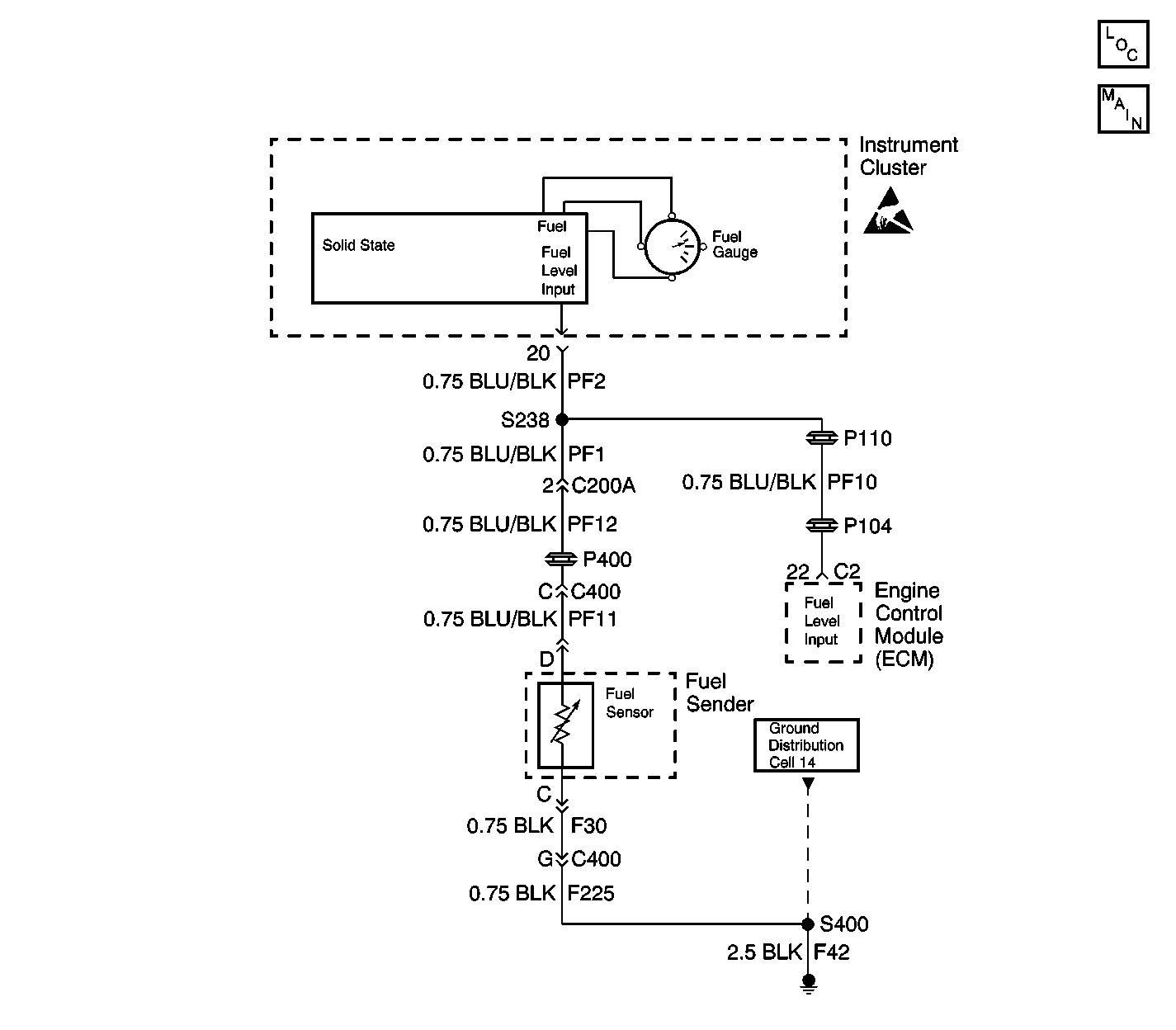
Circuit Description
The fuel tank sending unit consists of a float that rides on the surface of the fuel in the tank and a variable resistor controlled by the float arm. When electric power is supplied to the fuel gauge, current flows through the gauge to the variable resistor and then to ground. The position of the display is determined by the amount of current flowing through the gauge. The fuel level sender signal circuit connects to the instrument cluster and a splice in this circuit provides a signal to the ECM.
As the fuel level decreases the sending unit resistance increases and when the fuel level increases the sending unit resistance decreases. The display of the correct fuel level is dampened slightly upon start-up (cycling of ignition) and will stabilize after approximately 12 seconds.
Conditions for Setting the DTC
| • | The fuel level sensor voltage at the ECM is greater than 4.8 volts or less than 0.1 volts. |
| • | The above condition is present for 1 second. |
Action Taken When the DTC Sets
The ECM will not illuminate the malfunction indicator lamp (MIL).
Conditions for Clearing the MIL/DTC
| • | A history DTC clears after forty consecutive warm-up cycles in which there are no failures reported by this diagnostic or any other non-emission related diagnostic. |
| • | The ECM battery voltage is interrupted. |
| • | The scan tool clears the MIL/DTC. |
Diagnostic Aids
Use a scan tool to view the voltage for the fuel level sender. The voltage should be between 0.1 and 4.8 volts in the engine data list. The voltage will be between 0.1 and 10 volts in the instrument panel data list. This is a normal condition. The ECM processes the signal voltage and displays the fuel level sensor voltage as approximately one half the actual circuit voltage. The measured voltage on the fuel level signal circuit will be the same as the voltage displayed in the instrument panel data list. This voltage will be approximately twice the voltage displayed in the ECM data list.
Test Description
The number below refers to the step number on the diagnostic table.
Step | Action | Values | Yes | No |
|---|---|---|---|---|
1 | Did you perform the On-Board Diagnostic (OBD) System Check? | -- | Go to Step 2 | |
Is DTC 167 or DTC 168 set? | -- | Go to DTC 167 Fuel Gauge Voltage Low or DTC 168 Fuel Gauge Voltage High in Instrument Panel, Gauges and Console | Go to Step 3 | |
3 |
Did you find and repair a problem? | -- | Go to Step 6 | Go to Step 4 |
4 |
Did you find and repair a problem? | -- | Go to Step 6 | Go to Step 5 |
5 |
Important: This vehicle is equipped with a theft deterrent system that interfaces with the engine control module (ECM). Program the new ECM with the frequency code of the module that is currently on the vehicle. Replace the ECM. Refer to Engine Control Module Replacement/Programming . Is the action complete? | -- | Go to Step 6 | -- |
6 |
Does the scan tool indicate that the diagnostic Passed? | -- | Go to Step 7 | Go to Step 2 |
7 | Does the scan tool display any additional, undiagnosed DTCs? | -- | Go to the applicable DTC table | System OK |
