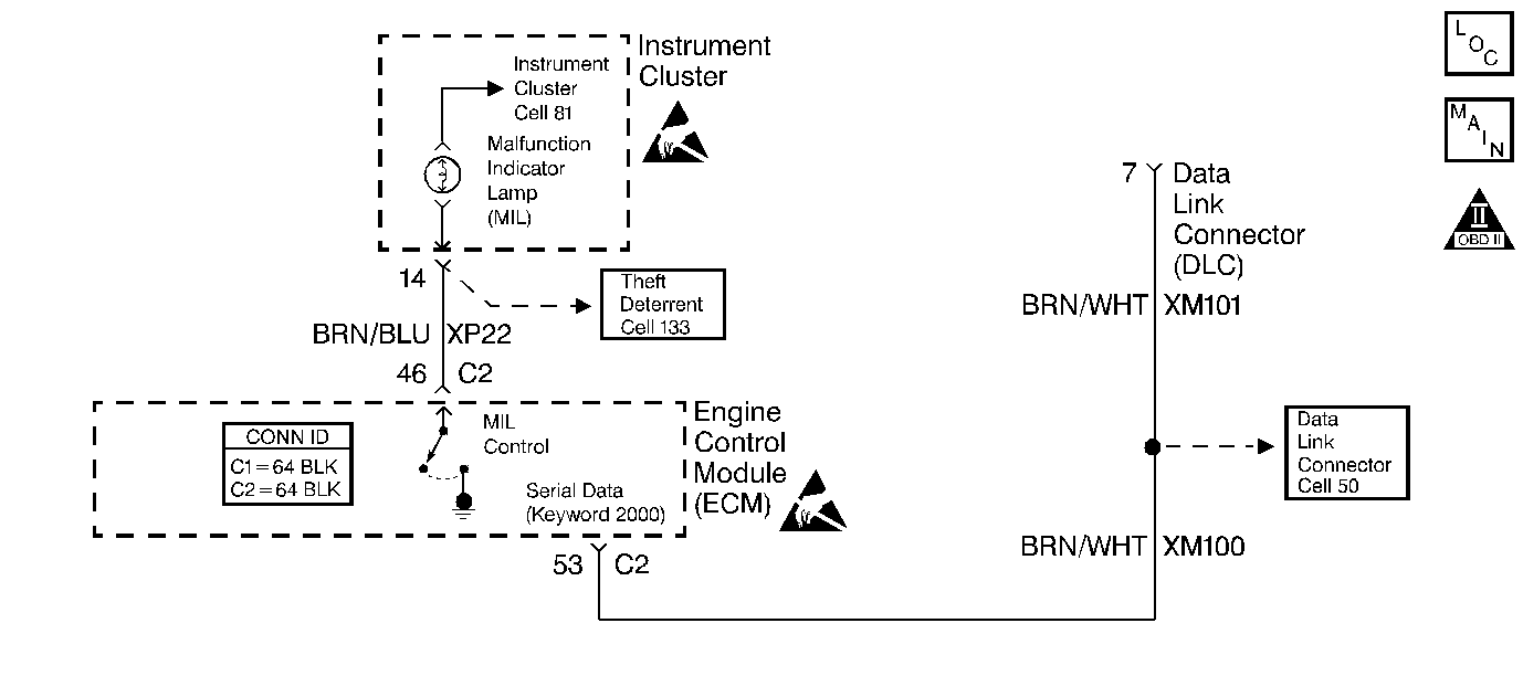
Circuit Description
There should always be a steady malfunction indicator lamp (MIL) when the ignition switch is on and the engine is not running. The ignition voltage is supplied within the instrument cluster to the indicator bulb. The engine control module (ECM) controls the lamp by grounding the control circuit via an internal solid state device called a driver.
Conditions for Running the DTC
| • | The engine speed must exceed 40 RPM. |
| • | The battery voltage must be between 7.5 and 14 volts. |
Conditions for Setting the DTC
The ECM determines there is an open, a short to ground or a short to voltage in the MIL control circuit.
Action Taken When the DTC Sets
The ECM illuminates the malfunction indicator lamp (MIL) and records the operating conditions in the Freeze Frame on the second consecutive drive trip that the diagnostic runs and fails.
Conditions for Clearing the MIL/DTC
| • | The ECM turns OFF the MIL after three consecutive drive trips that the diagnostic runs and passes. |
| • | A History DTC clears after forty consecutive warm-up cycles in which no failures are reported by this diagnostic or any other emission related diagnostic. |
| • | The ECM battery voltage is interrupted. |
| • | The scan tool clears the MIL/DTC. |
Diagnostic Aids
Notice: Using the J 35616-A Connector Test Adapter Kit will prevent damage to the harness connector terminals.
| • | Use the J 35616 Connector Test Adapter Kit for any test that requires probing the ECM harness connector or a component harness connector. |
| • | If the ignition feed circuit is suspected of being open, check if the other bulbs on that circuit illuminate. |
| • | Check to see if instrument panel fuse 15 is open. |
| • | An intermittent may be caused by the following: |
| - | Corrosion |
| - | A mis-routed harness |
| - | A rubbed through wire insulation |
| - | A broken wire inside the insulation |
Refer to Symptoms for the Intermittents.
Test Description
The numbers below refer to the step numbers on the diagnostic table.
-
The MIL should remain ON when the ignition is turned ON and the engine is OFF.
-
If the other indicator lamps in the instrument cluster are functioning, the feed circuit is OK.
-
After the engine starts, the MIL should illuminate briefly and turn OFF.
Step | Action | Values | Yes | No | ||||||
|---|---|---|---|---|---|---|---|---|---|---|
1 | Did you perform the Powertrain On-Board Diagnostic (OBD) System Check? | -- | ||||||||
Turn ON the ignition, leaving the engine OFF. Does the MIL illuminate? | -- | |||||||||
Check the fuse for the instrument cluster ignition feed circuit. Is the fuse OK? | -- | |||||||||
4 |
Is the MIL ON? | -- | ||||||||
5 | Check for the following conditions:
Is the action complete? | -- | -- | |||||||
6 | Command the MIL OFF using the scan tool. Does the MIL turn OFF? | -- | Go to Diagnostic Aids | |||||||
7 |
Does the MIL illuminate? | -- | ||||||||
8 | Repair the short to ground in the MIL control circuit. Refer to Wiring Repairs in Wiring Systems. Is the action complete? | -- | -- | |||||||
9 | Repair the short to ground in the feed circuit to the instrument panel indicator lamps. Refer to Wiring Repairs in Wiring Systems. Is the action complete? | -- | -- | |||||||
10 | Check for a poor connections or poor terminal tension at the ECM harness connector. Refer to Engine Control Module Diagnosis for proper procedure. Did you find and correct a problem? | -- | ||||||||
11 |
Important:
Replace the ECM. Refer to Engine Control Module Replacement/Programming . Is the action complete? | -- | -- | |||||||
Does the scan tool indicate that the diagnostic Passed? | -- | System OK |
