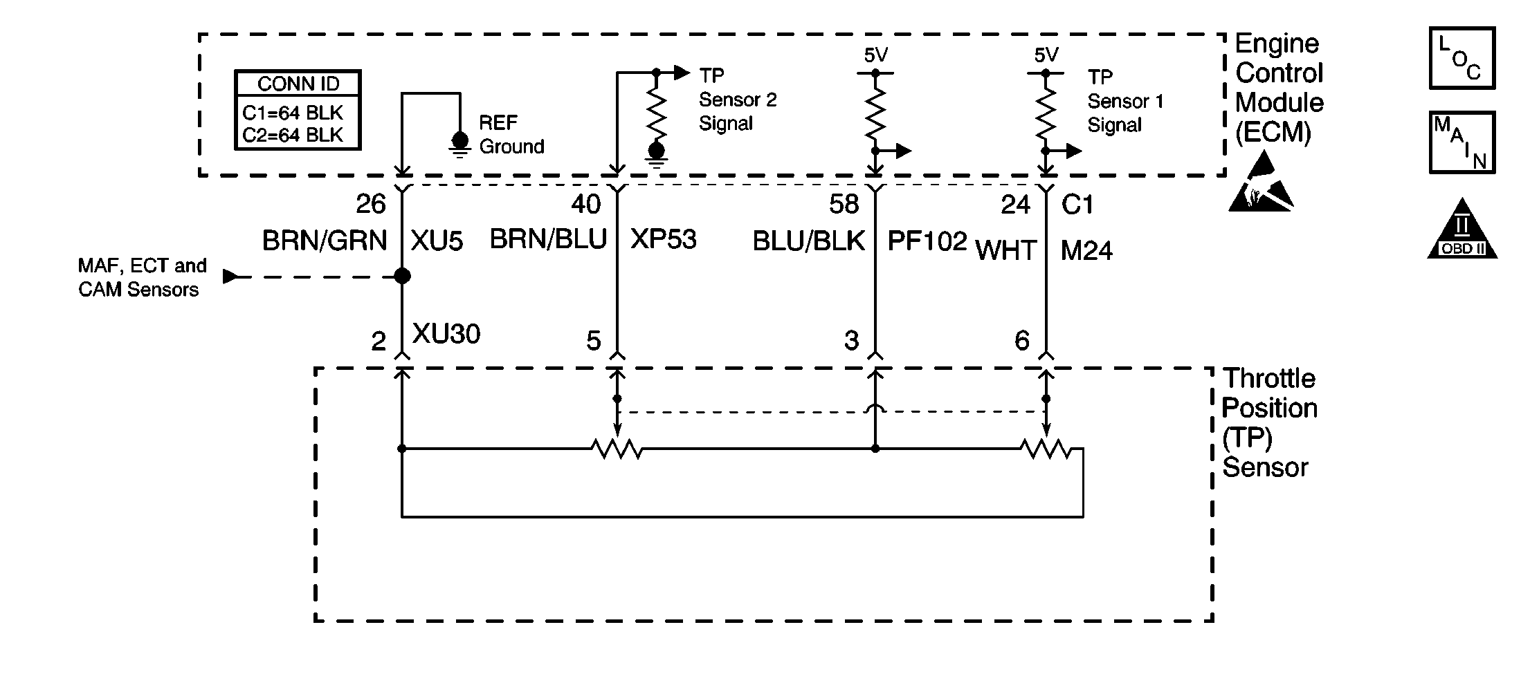
Circuit Description
The ECM tests the ability of the throttle blade to operate in the limp home throttle angle opening. When the correct operating conditions are met the ECM will command the throttle blade to the limp home throttle angle opening. If the throttle blade does not operate in the desired throttle range this DTC will set.
Conditions for Running the DTC
| • | The vehicle speed is 0 MPH. |
| • | The engine speed is less than 250 RPM. |
| • | The engine coolant temperature (ECT) is between 5°C (41°F) and 100°C (212°F). |
| • | The intake air temperature (IAT) is more than 5°C (41°F). |
| • | The battery voltage is greater than 10 V. |
| • | The accelerator pedal position (APP) is less than 15 percent. |
Conditions for Setting the DTC
The throttle position (TP) angle is less than 3.7 percent, or greater than 9.8 percent.
Action Taken When the DTC Sets
The ECM illuminates the malfunction indicator lamp (MIL) and records the operating conditions in the Freeze Frame on the first drive trip that the diagnostic runs and fails.
Conditions for Clearing the MIL/DTC
| • | The ECM turns off the MIL after 3 consecutive drive trips that the diagnostic runs and passes. |
| • | A History DTC clears after forty consecutive warm-up cycles if no failures report by this diagnostic or any other emission related diagnostic. |
| • | The ECM battery voltage is interrupted. |
| • | The scan tool clears the MIL/DTC. |
Diagnostic Aids
Inspect the throttle body blade. the blade should return completely to its stop. The DTC will set when the blade does not return to its stop.
Step | Action | Values | Yes | No |
|---|---|---|---|---|
1 | Did you perform the Powertrain On-Board Diagnostic (OBD) System Check? | -- | Go to Step 2 | |
2 | Diagnose and repair any electronic throttle control DTCs before proceeding. Are any other DTCs displayed? | -- | Go to the applicable DTC table | Go to Step 3 |
3 | Visually inspect the throttle body to ensure that the throttle body valve is in the closed position. Is the throttle valve closed? | -- | Go to Step 4 | Go to Step 7 |
4 |
Is the voltage within the specified range? | 0.16-.080 V (TP1) 4.0-4.8 V (TP2) | Go to Step 8 | Go to Step 5 |
5 | Inspect the TP sensor 1 and TP sensor 2 circuitry for an open, a short to ground, a short together or resistance. Did you find a faulty circuit? | -- | Go to Step 6 | Go to Step 8 |
6 | Repair the circuit as necessary. Refer to Wiring Repairs in Wiring Systems. Did you complete the repair? | -- | Go to Step 9 | -- |
7 | Replace the throttle body assembly. Refer to Throttle Body/Throttle Position Sensor Replacement . Did you complete the repair? | -- | Go to Step 9 | -- |
8 |
Important: This vehicle is equipped with a theft deterrent system that interfaces with the engine control module (ECM). Program the new ECM with the frequency code of the theft deterrent module that is currently on the vehicle. Replace the ECM. Refer to Engine Control Module Replacement/Programming . Is the action complete? | -- | Go to Step 9 | -- |
9 |
Does the scan tool indicate that the diagnostic Passed? | -- | Go to Step 10 | Go to Step 2 |
10 | Does the scan tool display any additional undiagnosed DTCs? | -- | Go to the applicable DTC table | System OK |
