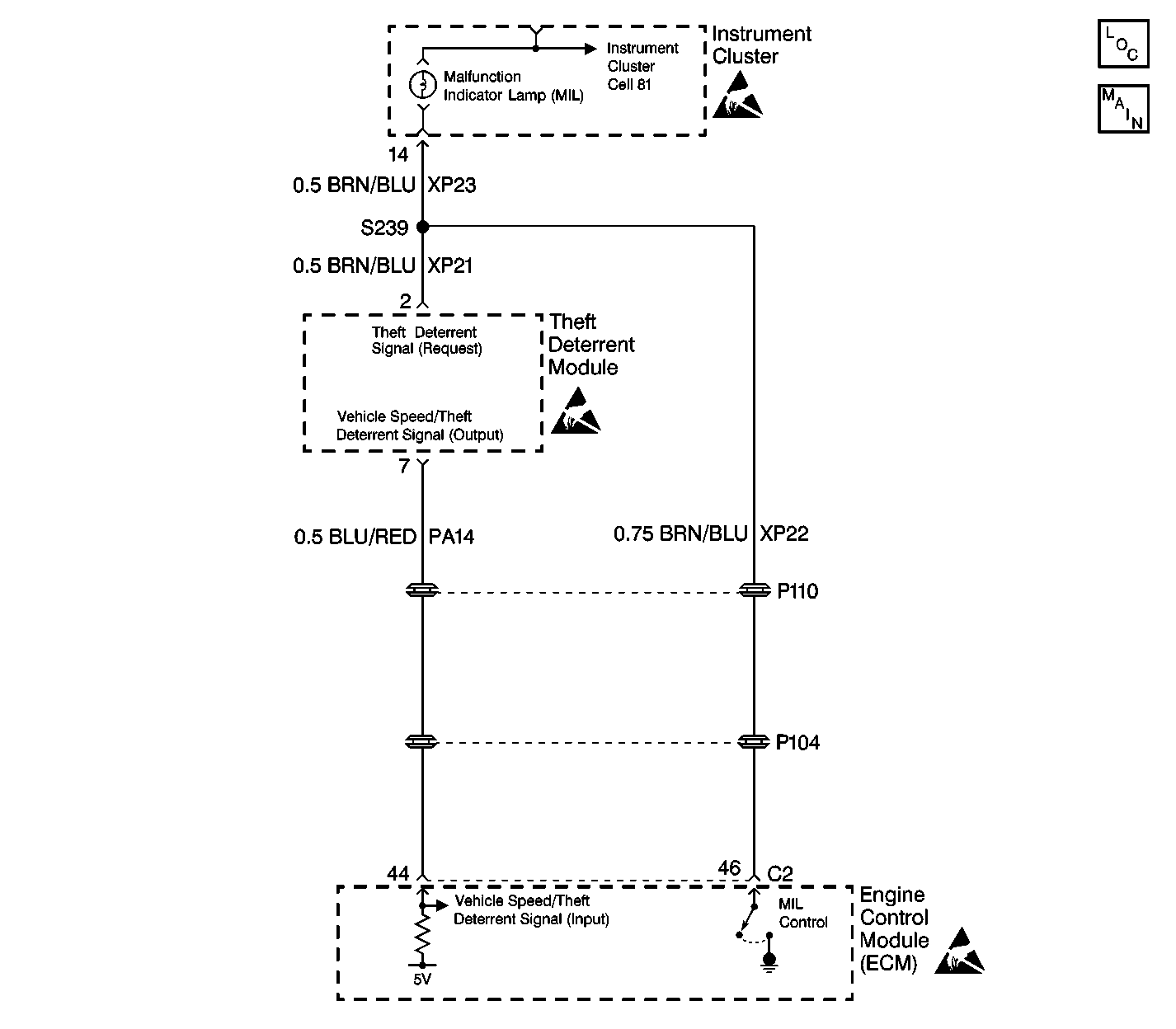
Circuit Description
When the ignition switch is turned ON, the engine control module (ECM) sends a signal over the lamp circuit to terminal 2 of the theft deterrent module (immobilizer) requesting the frequency code (imo signal).
After the theft deterrent module (TDM) receives and recognizes the transponder code signal from the key, the module internally switches from the speed signal circuit and sends the imo signal to the ECM from terminal 7. The ECM receives the imo signal at terminal 44.
Conditions for Setting the DTC
| • | A DTC 18 sets when the imo request signal from the ECM is inaccurate or erratic. |
| • | A short to ground in the imo request circuit |
| • | An open in the imo request circuit |
| • | All the above conditions must be fulfilled for at least 0.51 seconds. |
Action Taken When the DTC Sets
| • | The MIL does not illuminate when the conditions for setting this DTC is due to an open in the imo request circuit. |
| • | The TDM stores a DTC 17 and/or DTC 18 in memory. |
Conditions for Clearing the DTC
| • | Conditions for the fault are no longer present. |
| • | Use a scan tool in order to clear this DTC. |
Diagnostic Aids
Inspect for the following conditions if a history or intermittent DTC is indicated:
| • | A poor connection at the TDM or ECM |
| Inspect the wiring harness connectors for backed out terminals, improper mating, improperly formed or damaged terminals, and poor terminal to wire connections. |
| • | A damaged wiring harness |
| Inspect the wiring harness for damage. If the wiring harness appears to be in good condition, observe the display on the DMM while moving the connectors and wiring harnesses related to the TDM and ECM. |
| • | For additional information, refer to Intermittents and Poor Connections Diagnosis in Wiring Systems. |
Inspect for the following conditions before replacing the theft deterrent module:
| • | Test the ground circuit at terminal 4 (BLK). Perform a voltage drop test, refer to Measuring Voltage Drop in Wiring Systems. Typical voltage drop readings are 100mV or less. When measuring the resistance, the resistance should measure at close to 0 (zero) ohms. |
| • | Test the power circuits at terminal 5 (BRN) and terminal 9 (RED). |
Test Description
The number(s) below refer to the step number(s) on the diagnostic table.
-
The scan tool displays and indicates whether the theft deterrent module (TDM) has received a request signal from the engine control module (ECM).
-
If the DTC continues to reset and the circuits are OK, the possibility exists that either the TDM or the ECM may be at fault. The only way to determine which one is at fault is by trail and error. Replace the TDM first.
-
After determining that the TDM is OK, replace the ECM.
Step | Action | Value(s) | Yes | No |
|---|---|---|---|---|
1 | Did you perform the Theft Deterrent System Check? | -- | Go to Step 2 | |
Does the scan tool display the parameter RECEIVED? | -- | Go to Step 7 | Go to Step 3 | |
3 |
Is the measured voltage equal to the specified value? | B+ | Go to Step 9 | Go to Step 4 |
4 | Test for a short to ground in CKT XP21 (BRN/BLU). Did the test results indicate a short to ground? | -- | Go to Step 5 | Go to Step 6 |
5 | Locate and repair the short to ground in CKT XP21 (BRN/BLU). Did you complete the repair? | -- | -- | |
6 | Locate and repair an open in CKT XP21 (BRN/BLU). Did you complete the repair? | -- | -- | |
7 | Inspect for a possible intermittent malfunction. Refer to Intermittents and Poor Connections Diagnosis in Wiring Systems. Was an intermittent problem found? | -- | Go to Step 8 | Go to Step 9 |
8 | Locate and repair the intermittent problem. Is the repair complete? | -- | -- | |
9 |
Is a current DTC 17 or DTC 18 present? | -- | Go to Step 10 | |
Is the repair complete? | -- | Go to Step 11 | -- | |
11 |
Does the scan tool display RECEIVED? | -- | Go to Step 12 | |
Does the scan tool display RECEIVED? | -- | -- |
