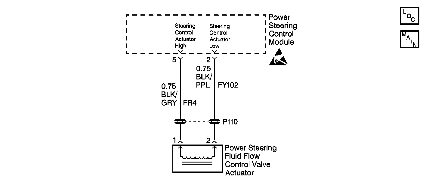
Circuit Description
The power steering control module (PSCM) determines current flow of the power steering fluid flow control valve actuator (solenoid) which is relative to the vehicle speed.
The solenoid converts the electrical signal into a corresponding hydraulic control variable, which determines the amount of reaction pressure and thus the steering force.
Conditions for Setting the DTC
| • | Short to ground or open in CKTs FR4 (BLK/GRY) or FY102 (BLK/PPL). |
| • | A defective power steering control valve actuator. |
Action Taken When the DTC Sets
| • | Power steering assist will default to partial manual steering effort. |
| • | The PSCM will store a DTC 22 in memory. |
Conditions for Clearing the DTC
| • | Conditions for the fault are no longer present. |
| • | Using the scan tool. |
Diagnostic Aids
Check for the following conditions if a history or intermittent DTC is indicated.
| • | A poor connection at the PSCM. Inspect the harness connectors for backed out terminals, improper mating, improperly formed or damaged terminals, and poor terminal to wire connections. |
| • | A damaged wiring harness. Inspect the wiring harness for damage. If the wiring harness appears to be in good condition, observe the display on the DMM while moving the connectors and wiring harnesses related to the actuator. A change in the DMM display during the test will indicate the location of the fault. |
| • | For additional information, refer to Intermittents and Poor Connections Diagnosis in Wiring Systems. |
Test Description
The number(s) below refer to the step number(s) on the diagnostic table.
-
This test checks for an open circuit in the wiring and control valve actuator windings.
-
This test checks for a short to ground in both circuit FY102 and FR4.
-
Before replacing the module, check the power and ground circuits.
-
This step determines after all repair attempts and DTC 22 is still present, that an internal malfunction exists in the Power Steering Control Module.
Step | Action | Value(s) | Yes | No |
|---|---|---|---|---|
1 | Was the Variable Effort Steering System Check performed? | -- | ||
2 |
Is a current DTC 22 displayed? | -- | ||
Is the measured resistance within the specified value? | 7-8 ohms | |||
4 | Check for a history or an intermittent DTC 22. Is a history or an intermittent DTC 22 displayed? | -- | ||
5 |
Is the repair complete? | -- | -- | |
Is the measured resistance for both measurements within the specified value? | OL | |||
7 |
Is the repair or replacement complete? | -- | -- | |
Is the replacement complete? | -- | -- | ||
9 |
Is the repair complete? | -- | -- | |
Is DTC 22 displayed? | -- | System OK |
