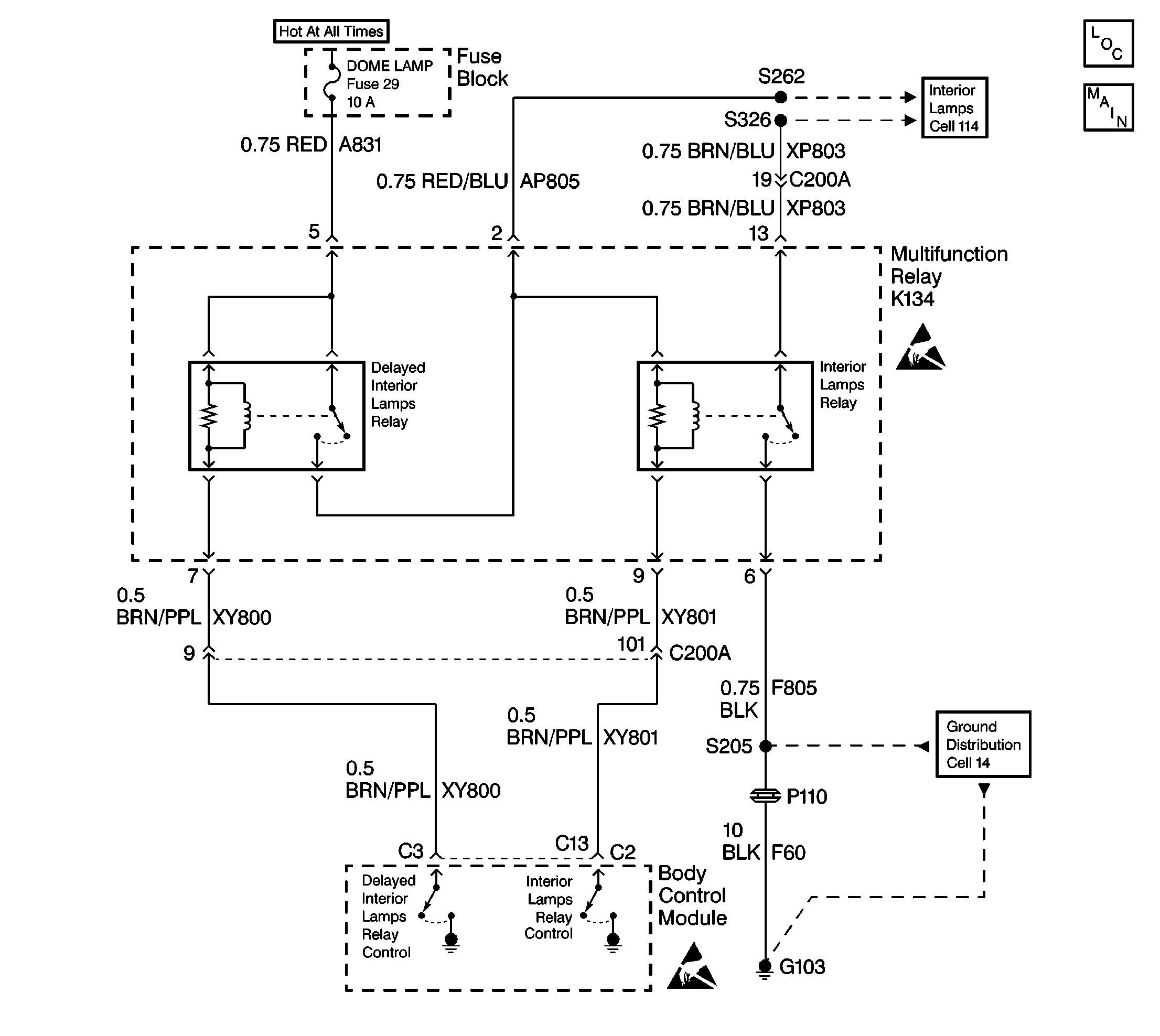
Circuit Description
The delayed interior lighting (DIL) feature, a battery guard for the courtesy lamps, provides automatic shutoff of all the interior lamps if the lamps are accidently left ON (inadvertent power).
The body control module (BCM) deactivates the output to the DIL relay when any of the following occurs:
| • | 10 minutes after the ignition switch transitions from ON to OFF |
| • | The ignition switch in the Start position |
The 10 minute timeout period resets anytime the BCM wakes up and any of the following states are detected:
| • | Illuminated Entry: |
| - | A door is opened or closed. |
| - | A RFA Class 2 message is received (driver door unlock). |
| - | An input (unlock) message is received from the drivers door lock switch. |
| • | The trunk lid is opened or closed. |
| • | The interior lights are turned On from the headlamp switch. |
The BCM continues to energize the DIL relay when the ignition switch is in the On position. No timeout period occurs in this position. When the DIL relay is energized it supplies power to the interior lights and the high side of the interior lamp relay coil.
Conditions for Setting the DTC
The BCM monitors the output to the DIL relay every second at terminal C3. The fault code sets when the commanded state doesn't match the feedback for 2 seconds (open circuit, short to B+ or ground).
Action Taken When the DTC Sets
| • | The BCM continues to command the requested state of the relay until it is achieved or is no longer necessary. |
| • | Stores a DTC B1971 in the BCM memory. |
Conditions for Clearing the DTC
| • | The conditions for the fault are not longer present. |
| • | The use of the scan tool. |
| • | A history DTC clears after 50 consecutive ignition cycles if the condition for the fault is no longer present. |
Diagnostic Aids
| • | Refer to the relay box end view for terminal assignments when the diagnostics direct you to take electrical measurements at the relay box. The end view is located in Power and Grounding Component Views in Wiring Systems. |
| • | Test the following if the problem is intermittent: |
| - | A damaged wiring harness. Inspect the wiring harness for damage. |
| - | If the wiring harness appears to be in good condition, observe the display on the DMM while moving connectors and wiring harnesses related to the BCM. |
| - | Inspect the wiring harness connectors for backed out terminals, improper mating, improperly formed or damaged terminals, and poor wire terminal to wire connections. |
| • | For additional information, refer to Intermittents and Poor Connections Diagnosis in Wiring Systems. |
Test Description
The following numbers refer to the step numbers on the diagnostic table:
-
When the DIL relay is commanded On/Off the status should match the commanded state. In most cases, a no change in status indicates a circuit problem.
-
This step tests for an intermittent condition in the circuit because the problem is not current at this time.
-
This test measures the resistance of the relay coil. An open coil winding sets this DTC. The DIL relay is contained in the multifunction relay and cannot be serviced separately.
Step | Action | Value(s) | Yes | No |
|---|---|---|---|---|
1 | Did you perform the BCM Diagnostic System Check? | -- | Go to Step 2 | |
Did the feedback status change with the commanded state? | -- | Go to Step 3 | Go to Step 4 | |
Problem is not current, test CKTs A831 (RED) and XY800 (BRN/PPL) for poor connections. Was a problem found and repaired? | -- | Go to Step 13 | ||
Is the measured resistance equal to the specified value? | OL | Go to Step 6 | Go to Step 7 | |
5 | Replace the BCM. Refer to Body Control Module Replacement . Is the replacement complete? | -- | -- | |
6 | Replace the multifunction relay. Is the replacement complete? | -- | -- | |
7 |
Is the measured resistance less than the specified value? | 2 ohms | Go to Step 8 | Go to Step 9 |
8 | Move the DMM probe from terminal 7 and connect it to a good ground. Is the measured resistance at the specified value? | OL | Go to Step 10 | Go to Step 11 |
9 | Repair the open circuit in CKT XY800. Is the repair complete? | -- | -- | |
10 |
Are the measured voltage readings less than the specified value? | 1.0 V | Go to Step 13 | Go to Step 12 |
11 | Repair the short to ground in CKT XY800. Is the repair complete? | -- | -- | |
12 | Repair the short to B+ in CKT XY800. Is the repair complete? | -- | -- | |
13 | Measure the voltage at terminal 5 of the multifunction relay. Is the voltage at the specified value? | B+ | Go to Step 15 | Go to Step 14 |
14 | Repair the open in CKT A831. Is the repair complete? | -- | Go to Step 15 | -- |
15 |
Does the BCM operate properly? | -- | System OK | -- |
