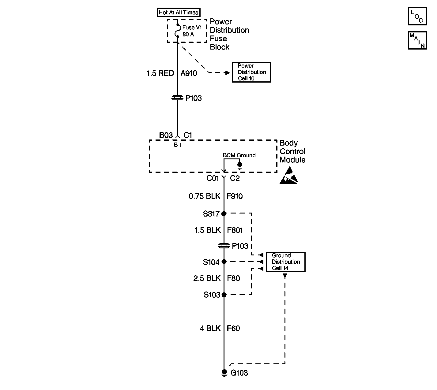
Circuit Description
Battery voltage is supplied to the body control module (BCM) at terminal B3. The BCM uses this power supply to perform most of its functions. The BCM constantly monitors the battery voltage at terminal B3.
Conditions for Setting the DTC
Battery voltage is tested every 300 ms. The fault code is set when the voltage is below 9.0 volts for 1200 ms.
Action Taken When the DTC Sets
Stores a DTC B1983 in the BCM memory.
Conditions for Clearing the DTC
| • | The BCM no longer detects a low voltage condition at terminal B3 for 1200 ms. |
| • | The use of a scan tool. |
| • | A history DTC will clear after 50 consecutive ignition cycles if the condition for the fault is no longer present. |
Diagnostic Aids
| • | Good terminal contact at B3. |
| • | A good clean and tight connection at G103 |
| • | Battery condition |
| • | For additional information regarding an intermittent condition or history DTC, refer to Intermittents and Poor Connections Diagnosis in Wiring Systems. |
Test Description
The following numbers refer to the step numbers on the diagnostic table:
-
This step tests the main battery feed circuit to the BCM.
-
This step tests for a possible intermittent connection and the ground circuit to the BCM. After testing these inputs, test the BCM again to see if the DTC resets, indicating an internal BCM failure.
Step | Action | Value(s) | Yes | No |
|---|---|---|---|---|
1 | Did you perform the BCM Diagnostic System Check? | -- | Go to Step 2 | |
Does the voltage measure less than the specified value? | 9.0 Volts | Go to Step 3 | Go to Step 4 | |
3 | Locate and repair the open circuit or excessive resistance in CKT A910. Is the repair complete? | -- | Go to Step 6 | -- |
Is a current DTC B1983 set? | -- | Go to Step 5 | Go to Step 6 | |
5 | Replace the BCM after confirming that voltage is not less than the specified value. Refer to Body Control Module Replacement . Is the replacement complete? | 9.0 Volts | -- | |
6 | Verify the BCM operation by turning on the headlamps, interior lamps, and cycling the door locks. Is the BCM operating properly? | -- | System OK |
