For 1990-2009 cars only
Tools Required
| • | J 21474-5 Control Arm Bushing Installer |
| • | J 42200 Rear Control Arm Bushing Bolt |
Removal Procedure
- Raise and support the vehicle. Refer to Lifting and Jacking the Vehicle in General Information.
- Remove the tire and wheel. Refer to Tire and Wheel Removal and Installation in Tires and Wheels.
- Remove the rear axle lower control arm. Refer to Rear Axle Lower Control Arm Replacement .
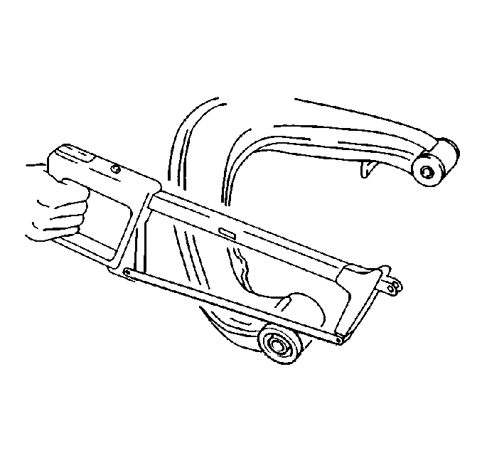
- Cut off the collar on the inboard lower control arm bushing.
- Cut off the rubber collar on the outboard lower control arm.
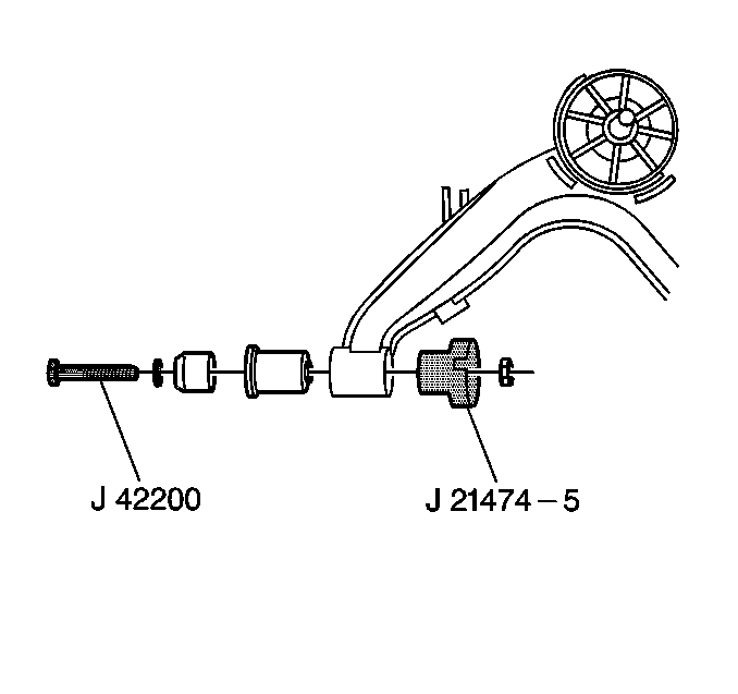
- Use the following to press out the bushing:


| • | 30 mm socket |
| • | J 42200 |
Installation Procedure
- Coat the new bushings with lubricant to enable ease of installation.
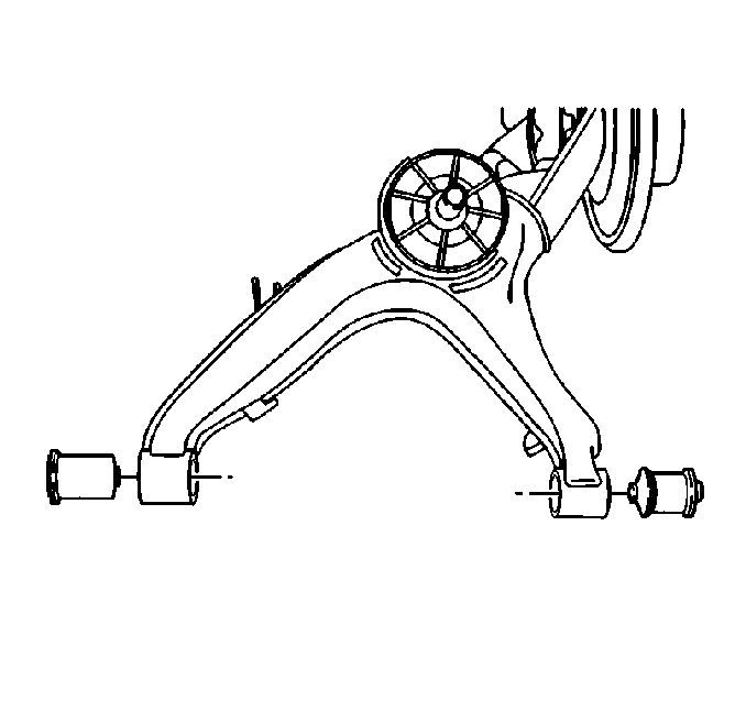
- Install the inboard side bushing with the collar toward the rear differential.
- Use the following tools to press in the new bushing:
- Lubricate the outboard side bushing with silicone spray.
- Install the outboard side bushing.
- Use the following to press in the new bushing:
- Install the rear axle lower control arm. Refer to Rear Axle Lower Control Arm Replacement .
- Install the tire and wheel. Refer to Tire and Wheel Removal and Installation in Tires and Wheels.
- Lower the vehicle.

| • | 30 mm socket |
| • | J 42200 |


| • | 30 mm socket |
| • | J 42200 |
