Removal Procedure
Tools Required
J 34730-1A Fuel Pressure Guage,J 41081
- Relieve the fuel system pressure.
- Refer to Fuel Pressure Relief Procedure .
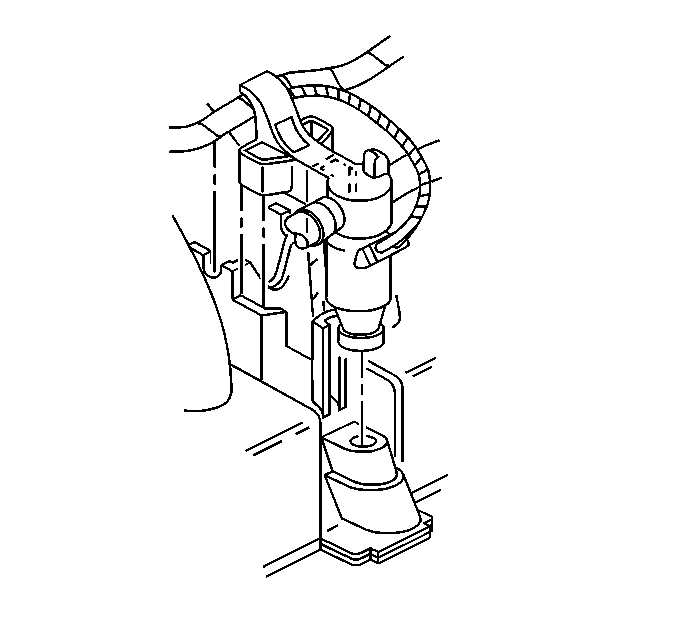
- Remove the injector electrical connector.
- Release the fuel rail to intake manifold locking tab by pushing toward center of intake manifold.
- Pry the injector up out of intake manifold using J 41081 between the bottom of injector and intake manifold.
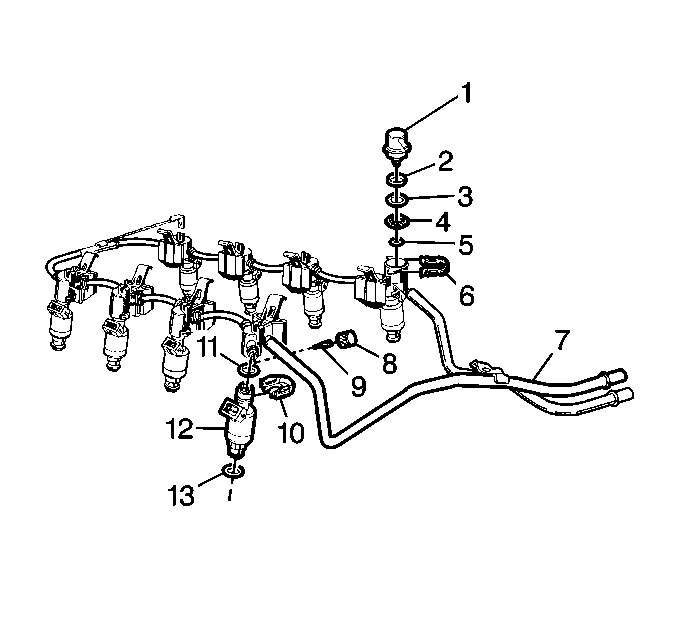
- Spread the injector retainer clip (10) to release injector from fuel rail.
- Remove the fuel injector assembly (1).
- Remove the upper (11) and lower (13) injector O-rings seals from the injector (12).
- Discard the injector O-ring seals.


Important: It may be necessary to release the adjacent injector(s) from the intake manifold to allow increased fuel rail movement for injector access.
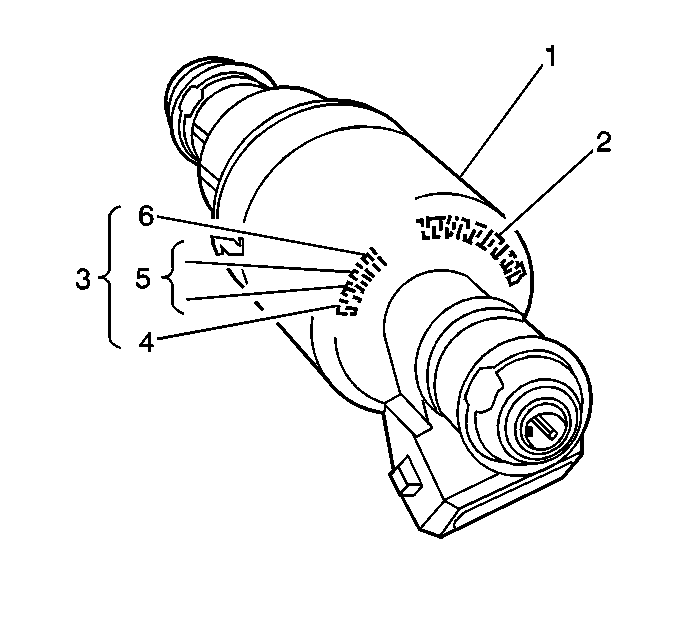
Important: When replacing a fuel injector, it may be necessary to have the following identification information. The fuel injector assembly contains the part number identification (2), the build date code (3), the month (4) 1-9 (Jan-Sept) O, N, D (Oct, Nov, Dec), the day (5), and the year (6).


Installation Procedure
Caution: In order to reduce the risk of fire and personal injury that may result from a fuel leak, always install the fuel injector O-rings in the proper position. If the upper and lower O-rings are different colors (black and brown), be sure to install the black O-ring in the upper position and the brown O-ring in the lower position on the fuel injector. The O-rings are the same size but are made of different materials.
- Lubricate the new upper (11) and lower (13) O-rings with clean engine oil.
- Install the new upper (11) and lower injector (13) O-rings on the injector (12).
- Install the fuel injector (12) into fuel rail.
- Snap the fuel rail down onto intake manifold.
- Install the injector electrical connector.
- Tighten the fuel filler cap.
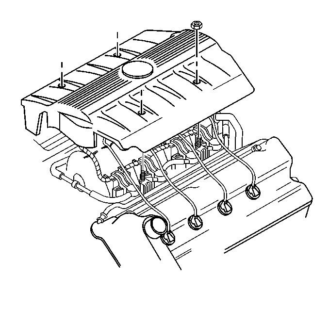
- Install the intake manifold top cover.
- Install the negative battery cable. Refer to Battery.

| • | Ensure injectors are aligned by orientating electrical connector perpendicular to crankshaft. |
| • | Push in the retainer clip (10) far enough to engage retainer clip with machined slots on rail socket. |

| 6.1. | Turn ignition switch to ON position for 2 seconds. |
| 6.2. | Turn the ignition switch OFF for 10 seconds |
| 6.3. | Turn the ignition switch ON. |
| 6.4. | Check for fuel leaks. |

Tighten
Tighten the nuts to 2 N·m (18 lb in).
Refer to the
Notice: Use the correct fastener in the correct location. Replacement fasteners must be the correct part number for that application. Fasteners requiring replacement or fasteners requiring the use of thread locking compound or sealant are identified in the service procedure. Do not use paints, lubricants, or corrosion inhibitors on fasteners or fastener joint surfaces unless specified. These coatings affect fastener torque and joint clamping force and may damage the fastener. Use the correct tightening sequence and specifications when installing fasteners in order to avoid damage to parts and systems.
in General Information