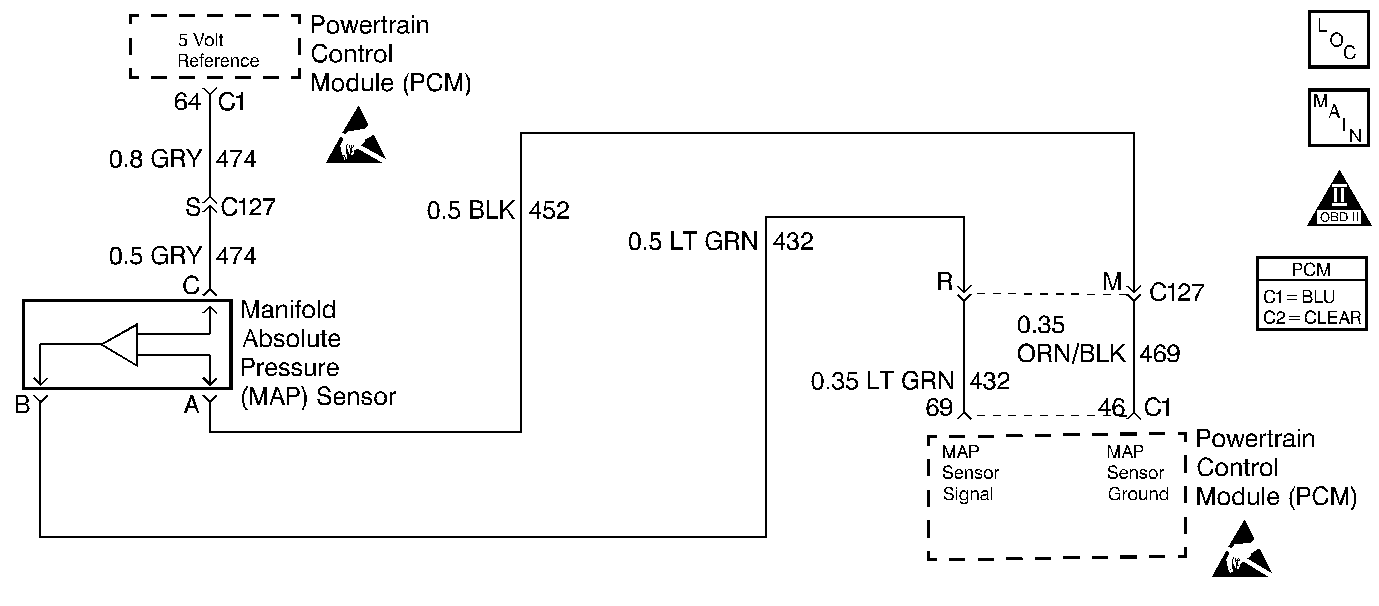
Circuit Description
This diagnostic test is designed to determine when the MAP sensor is sticking. The PCM does this by checking for throttle position changes that are not immediately followed by MAP signal changes. When a throttle position change of 3.2 degrees in 0.5 second occurs, the PCM watches the MAP signal for one second following the throttle position change. If the MAP signal does not change by at least 4 kPa in this period and the MAP sensor reading is more than 17.3 kPa different than the expected MAP reading, based on engine speed and throttle position. If this condition is repeated 5 times then DTC P0105 will set.
Conditions for Setting the DTC
Test Conditions
| • | DTCs P0106, P0107, P0108, P0122, P0123 and P1108 not set. |
| • | MAP is at least 21.5 kPa. |
| • | Engine vacuum is at least 11.8 kPa. |
Failure Condition
MAP signal changes less than 4 kPa in the one second following a 3.2 degree change in throttle position and the MAP signal is not within 17.3 kPa of the expected MAP reading. This must occur 5 times.
Action Taken When the DTC Sets
| • | The PCM subtitutes calculated MAP for actual MAP. |
| • | The BARO value is set to 92.2 kPa. |
| • | The PCM will illuminate the malfunction indicator lamp (MIL) when the diagnostic runs and fails. |
| • | The PCM will record operating conditions at the time the diagnostic fails. This information will be stored in the Freeze Frame and Failure Records. |
Conditions for Clearing the MIL/DTC
| • | The PCM will turn the MIL OFF after three consecutive drive trips that the diagnostic runs and does not fail. |
| • | A Last Test Failed (current) DTC will clear when the diagnostic runs and does not fail. |
| • | A History DTC will clear after forty consecutive warm-up cycles with no failures of any emission related diagnostic test. |
| • | Use a scan tool to clear DTCs. |
| • | Interrupting PCM battery voltage may or may not clear DTCs. This practice is not recommended. Refer to Clearing Diagnostic Trouble Codes in PCM Description and Operation. |
Test Description
Number(s) below refer to the step number(s) on the Diagnostic Table.
-
Checking if the MAP sensor reading was lower than normal when the DTC set.
-
Checking if the MAP sensor reading was higher than normal when the DTC set.
-
Checking for poor terminal contact at all MAP sensor related connectors. If all terminal contacts are OK, the MAP sensor may be at fault.
Step | Action | Value(s) | Yes | No |
|---|---|---|---|---|
1 | Was the Powertrain On-Board Diagnostic (OBD) System Check performed? | -- | Go to A Powertrain On Board Diagnostic (OBD) System Check | |
2 |
Was MAP reading the same or less than the value specified? | 0.08 volts | Go to DTC P0107 Manifold Absolute Pressure (MAP) Sensor Circuit Low Voltage | |
3 | Was MAP reading the same or more than the value specified? | 5.06 volts | Go to DTC P0108 Manifold Absolute Pressure (MAP) Sensor Circuit High Voltage | |
4 |
Was terminal contact repaired? | -- | Go to Powertrain Control Module Diagnosis for Verify Repair | |
5 | Replace the MAP sensor. Is the replacement complete? | -- | Go to Powertrain Control Module Diagnosis for Verify Repair | -- |
