Rear Axle Lower Control Arm Bushing Replacement Suspension Support Forward
Removal Procedure
- Raise and support the vehicle. Refer to
Lifting and Jacking the Vehicle
in General Information.
- Remove the tire and wheel assemblies. Refer to
Wheel Removal
in Tires and Wheels.
- Remove the brake bracket retainer screw.
- Disconnect the road sensing suspension position sensor and the
bracket from the shock tower.
- Lower the exhaust system and heat shield, if you are replacing
the right side bushing.
- Install the screw jack under the rear suspension support forward
arm.

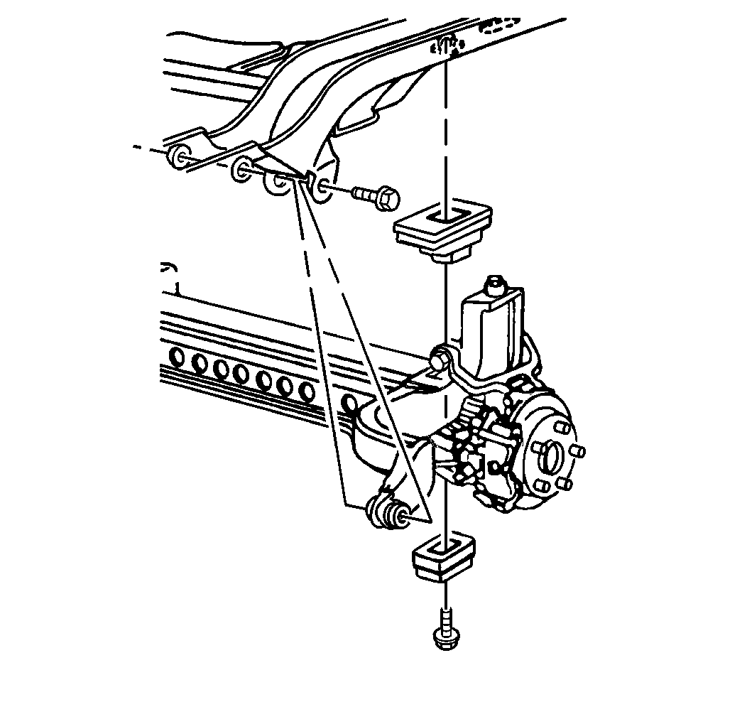
- Remove the forward arm
nuts and bolts.
Important: While lowering the suspension support, carefully watch the position
of the brake calipers, hoses and pipes in order to prevent damage during the
removal procedure.
- Slowly lower the forward arm only as far as required in order to gain
tool clearance (approximately 5 inches).
- Insert the J 35739 Rear Control Arm Bushing Service Set
between the forward arm flanges.
- Coat the threads of the J 21474-19
with High Pressure Lubricant in order to prevent thread
damage.
- Install the J 35739 Rear Control Arm Bushing Service Set
, the J 21474-5
, the J 21474-18
and the J 21474-19
.

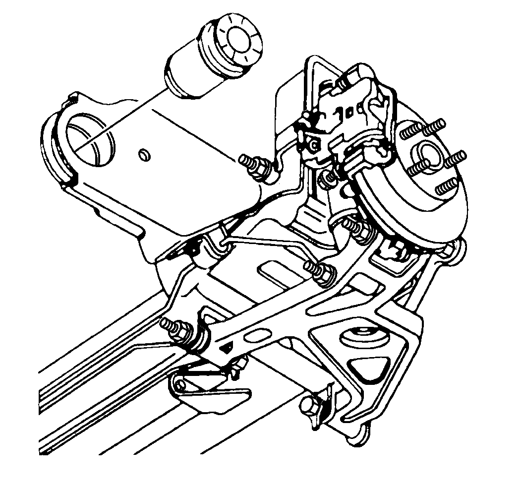
- Draw the bushing out of
the forward arm by tightening the nut.
Installation Procedure

- Position the new bushing
for installation on the forward arm.
| • | The bushing must be installed with the notches on the bushing
flange at the 12 o'clock and 6 o'clock positions. |
| • | The bushing must be installed from the outboard side of the forward
arm and drawn inward toward the vehicle centerline. |
- Insert the J 35739 Rear Control Arm Bushing Service Set
between the forward arm flanges.
- Coat the threads of the J 21474-19
with High Pressure Lubricant in order to prevent thread
damage.
- Install the J 35739 Rear Control Arm Bushing Service Set
, the J 21474-5
, the J 21474-18
, and the J 21474-19
.
- Draw the bushing into the forward arm by tightening the nut. Tighten
the nut until the bushing flange seats firmly against the arm.

- Check the upper suspension
support insulators for proper positioning.
Important: While raising the suspension support, carefully watch the position of
the brake calipers, hoses and pipes. Reposition the calipers, pipes and hoses
as required in order to prevent interference or damage to the brake components.
- Slowly raise the suspension support. Align the suspension support with
the body as it is raised.
Notice: Use the correct fastener in the correct location. Replacement fasteners
must be the correct part number for that application. Fasteners requiring
replacement or fasteners requiring the use of thread locking compound or sealant
are identified in the service procedure. Do not use paints, lubricants, or
corrosion inhibitors on fasteners or fastener joint surfaces unless specified.
These coatings affect fastener torque and joint clamping force and may damage
the fastener. Use the correct tightening sequence and specifications when
installing fasteners in order to avoid damage to parts and systems.
Important:
| • | Both forward arm bolts must be installed in the proper direction,
with the nuts installed on the right side of the arm. |
| • | The cup-shaped washer is used on the left forward arm bolt installation
only. |
- Install the suspension support forward arm bolts, nuts and washers,
the upper mounting bolts and the insulators.
Tighten
| • | Tighten the right side suspension support forward arm nut to 63 N·m
(46 lb ft). |
| • | Tighten the left side suspension support forward arm bolt to 102 N·m
(75 lb ft). |
| • | Tighten the upper mounting bolts to 102 N·m (75 lb ft). |
- Remove the screw jacks.
- Install the exhaust system and the heat shield.
- Connect the Road Sensing Suspension position sensor and bracket
from the shock tower.
- Install the brake bracket retainer screw.
- Install the tire and wheel assemblies. Refer to
Wheel Installation
in Tires and Wheels.
- Lower the vehicle.


