Removal Procedure
- Remove the brake fluid from the master cylinder. Use a syringe to remove as much fluid as possible.
- Dispose of the brake fluid. Do not reuse.
- Reinstall the reservoir cap with the diaphragm.
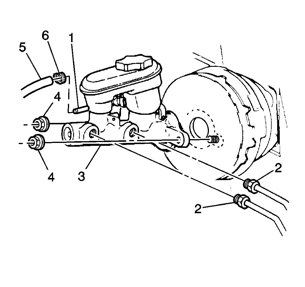
- Disconnect the electrical connector from the fluid level sensor switch.
- Remove the tube nuts.
- Remove the hydraulic lines.
- Plug the open hydraulic lines to prevent fluid loss and contamination.
- Remove the two attaching nuts.
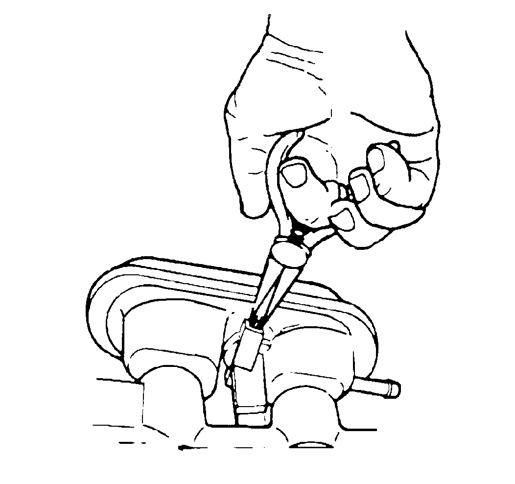
- Pinch off the rubber hose as close to the reservoir nozzle as possible. Use a pair of clamp-type pliers to prevent fluid loss.
- Move the master cylinder forward off of the booster studs and the lower flange end of the master cylinder. This will cause the reservoir nozzle to point up.
- Remove the hose clamp.
- Remove rubber hose from the reservoir nozzle.
- Remove master cylinder.

Do not damage the rubber hose or the reservoir nozzle.
Caution: Use shop cloths to prevent any brake fluid that may leak from master cylinder or rubber hose from contacting vehicle body or electrical connections.
Installation Procedure
- Install the master cylinder.
- Install the attaching nuts
- Connect the hydraulic lines. Install the tube nuts.
- Connect the rubber hose to the reservoir nozzle.
- Secure the hoses with a clamp.
- Connect the electrical connector to the fluid level sensor switch.
- Fill the master cylinder to the proper level with clean brake fluid.
- Bleed the hydraulic system. Refer to Hydraulic Brake System Bleeding .
- Recheck the fluid level.

Tighten
Tighten the master cylinder attaching nuts to 27 N·m (20 lb ft).
Notice: Use the correct fastener in the correct location. Replacement fasteners must be the correct part number for that application. Fasteners requiring replacement or fasteners requiring the use of thread locking compound or sealant are identified in the service procedure. Do not use paints, lubricants, or corrosion inhibitors on fasteners or fastener joint surfaces unless specified. These coatings affect fastener torque and joint clamping force and may damage the fastener. Use the correct tightening sequence and specifications when installing fasteners in order to avoid damage to parts and systems.
Tighten
Tighten brake pipe nuts to 15 N·m (11 lb ft).

Do not fill above the maximum level indicator.
