For 1990-2009 cars only
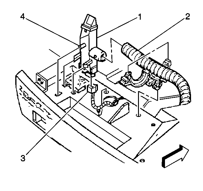
Inside Air Temperature Sensor Replacement Eldorado
Removal Procedure
- Disconnect the negative battery cable.
- Remove the instrument panel upper trim panel. Refer to Instrument Panel Upper Trim Pad Replacement in Instrument Panel, Gauges and Console.
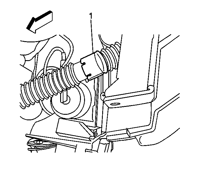
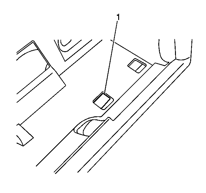
- Disconnect the aspirator hose (2) from the sensor (1).
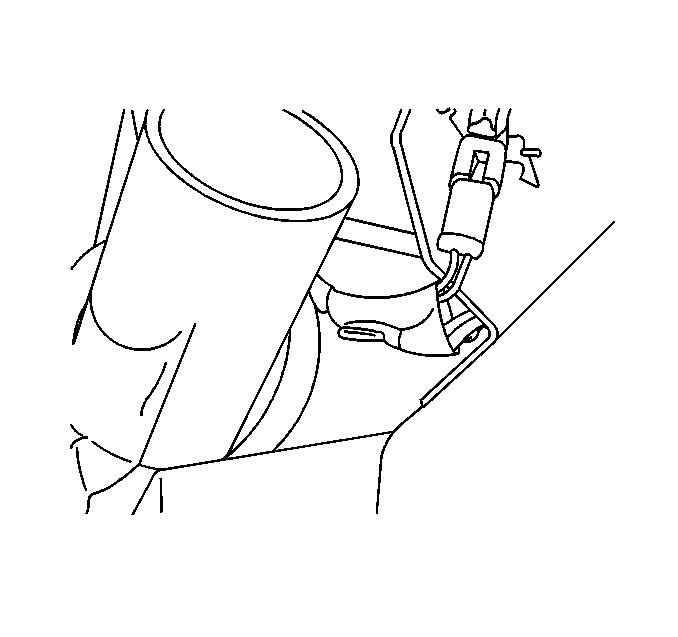
- Disconnect the electrical connector (3).
- Remove the retaining screw (4) from the inside air temperature sensor (1).
- Remove the inside air temperature sensor (1).
Caution: Unless directed otherwise, the ignition and start switch must be in the OFF or LOCK position, and all electrical loads must be OFF before servicing any electrical component. Disconnect the negative battery cable to prevent an electrical spark should a tool or equipment come in contact with an exposed electrical terminal. Failure to follow these precautions may result in personal injury and/or damage to the vehicle or its components.
Installation Procedure
- Secure the temperature sensor (1) with the retaining screw (4).
- Connect the electrical connector (3).
- Install the aspirator hose (2) to the sensor (1) and the clip.
- Install the instrument panel upper trim panel. Refer to Instrument Panel Upper Trim Pad Replacement in Instrument Panel, Gauges and Console.
- Connect the negative battery cable.
Inside Air Temperature Sensor Replacement DeVille
Removal Procedure
- Remove the instrument panel (IP) upper trim panel. Refer to Instrument Panel Upper Trim Pad Replacement in Instrument Panel, Gauges and Console.
- Remove the IP cluster. Refer to Instrument Cluster Replacement in Instrument Panel, Gauges and Console.
- Remove the left sound insulator. Refer to Instrument Panel Insulator Panel Replacement - Left Side in Instrument Panel, Gauges and Console.
- Remove the steering column filler. Refer to Steering Column Opening Filler Replacement in Instrument Panel, Gauges and Console.
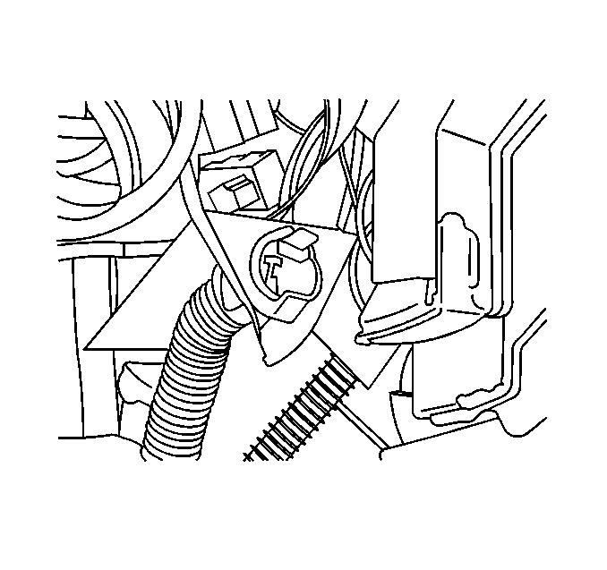
- Pull the inside air temperature sensor (1) towards the front of the dash in order to release the sensor clips from the IP.
- Disconnect the electrical connector.
- Remove the sensor.
Installation Procedure
- Route the sensor into the instrument panel (IP).
- Use a flat bladed screwdriver in order to aid in the alignment of the sensor clips into the IP.
- Once the sensor is aligned, use the screwdriver in order to install the sensor into the IP.
- Connect the electrical connector.
- Install the steering column filler. Refer to Steering Column Opening Filler Replacement in Instrument Panel, Gauges and Console.
- Install the left sound insulator. Refer to Instrument Panel Insulator Panel Replacement - Left Side in Instrument Panel, Gauges and Console.
- Install the IP cluster. Refer to Instrument Cluster Replacement in Instrument Panel, Gauges and Console.
- Install the IP upper trim panel. Refer to Instrument Panel Upper Trim Pad Replacement in Instrument Panel, Gauges and Console.
Insert the screwdriver through the access hole (1) in the IP.
