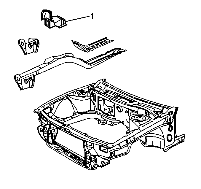
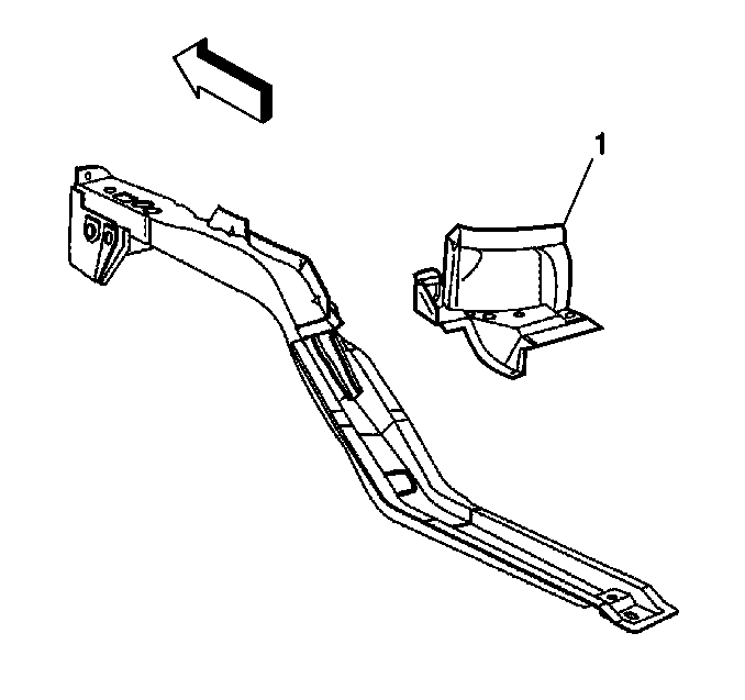
Lower Rail Sub-Assembly

The lower rail service part comes as a complete assembly, including all brackets and reinforcements. The front extension (1) can also be purchased as separate service part. The lower rail close-out panel must be ordered separately.
Lower Rail Close-Out Panel
The lower rail close-out panel is mounted to the lower edge of the cowl on the outboard side of the lower rail. The mid-section of the lower rail is sandwiched between this panel and the floor pan for added vehicle strength and rigidity. (1) It also serves as the mounting point for the power train cradle. When performing a full replacement of the lower rail, the lower rail close-out panel must also be removed and reinstalled, or replaced if necessary.
Important: Bumper mounting holes must be properly located and drilled . Use three dimensional measuring equipment.
Removal Procedure
- Support the power train and lower the cradle away from the lower rail. Note that it is not necessary to entirely remove the cradle.
- Remove all other related panels and components including the strut and axle assembly.
- Visually inspect and restore as much of the damage as possible to factory specifications.
- Locate, mark and drill out all factory welds. Note the number of welds for installation of the service assembly.
- Remove the damaged front lower rail and lower rail close-out panel (1).

Caution: Foam sound deadeners must be removed from areas within 152.4 mm (6 in) of where flame is to be used for body repairs. When reinstalling foam sound deadeners, avoid inhaling fumes as bodily injury may result.
Installation Procedure
- Prepare mating surfaces.
- Check for proper fit of the lower rail service assembly and the lower rail close-out panel.
- Drill 8 mm (5/16 in) plug weld holes on the service assembly and close-out panel in the locations noted from the original parts.
- Position the service assembly and close-out panel.
- To ensure proper fit, use three dimensional measuring equipment.
- Clean and prepare welded surfaces.
- Apply sealers and anti-corrosion materials as necessary.
- Prime with two-part catalyzed primer.
- Apply paintable sound deadening pads to floor as necessary to match original sound deadening.
- Install all related panels and components.

