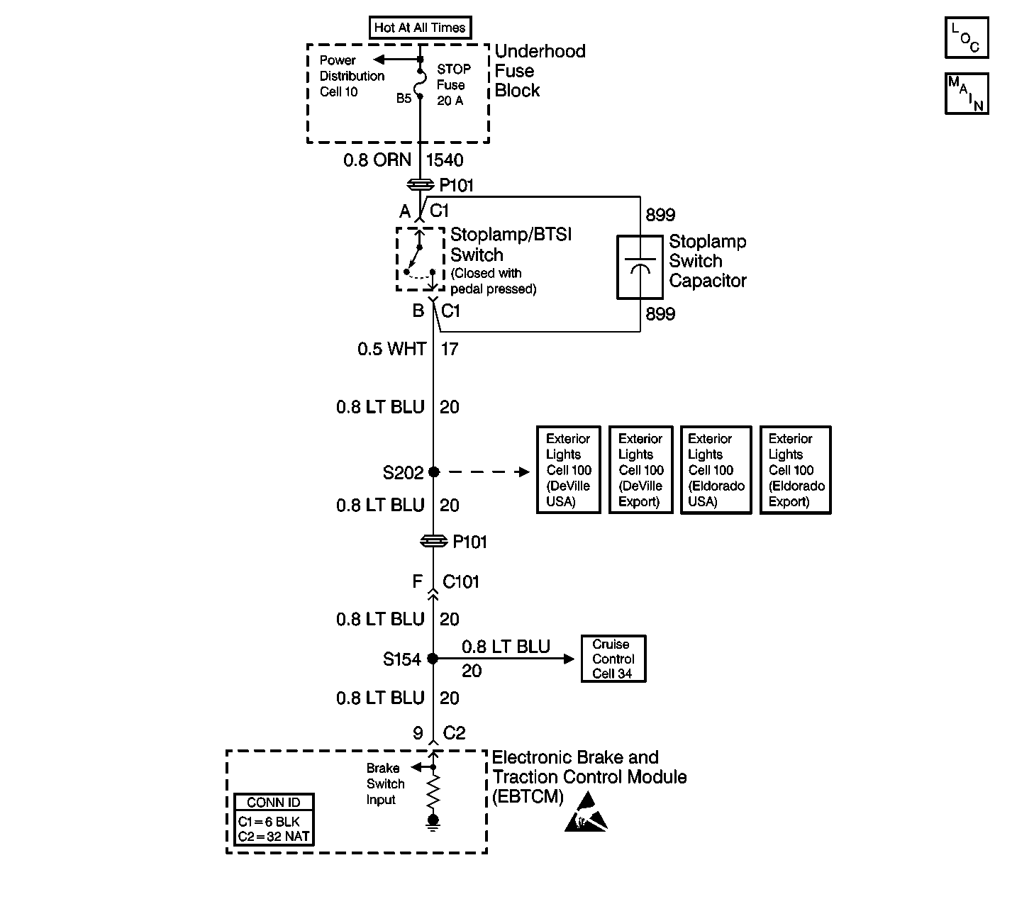
Circuit Description
The extended travel brake switch is used by the EBTCM to determine if the driver has pressed the brake pedal far enough to initiate moderate braking, as opposed to merely brushing or tapping the pedal. The PCM sends this information to the EBTCM via serial data class 2 messages.
Conditions for Setting the DTC
| • | The ignition is ON. |
| • | The PCM detects an extended travel brake switch failure. The PCM also set DTC P1575. |
Action Taken When the DTC Sets
| • | A malfunction DTC is stored. |
| • | Stabilitrak® is disabled. |
| • | The DIC displays the SERVICE STABILITY SYS message. |
| • | The ABS/TCS remain functional. |
Conditions for Clearing the DTC
| • | The condition for DTC is no longer present and you used scan tool Clear DTCs function. |
| • | The condition for DTC is no longer present and you used the On-Board Clear DTCs function. |
| • | The EBTCM does not detect the DTC in 50 drive cycles. |
Diagnostic Aids
| • | If the extended travel brake switch is not properly adjusted, the driver may experience longer Stabilitrak® brake pedal pulsations before normal brake pedal feel is returned. The Stabilitrak® brake pedal pulsation is different than the ABS brake pedal pulsation. The Stabilitrak® brake pedal pulsation has a much higher frequency and less pedal travel fluctuation. |
| • | It is very important that a thorough inspection of the wiring and connectors be performed. Failure to carefully and fully inspect wiring and connectors may result in misdiagnosis, causing part replacement with reappearance of the malfunction. |
| • | An intermittent malfunction can be caused by poor connections, broken insulation, or a wire that is broken inside the insulation. |
| • | If an intermittent malfunction exists, refer to Intermittents and Poor Connections . |
Step | Action | Value(s) | Yes | No |
|---|---|---|---|---|
1 | Was the Diagnostic System Check performed? | -- | Go to Step 2 | Go to Diagnostic System Check |
2 | Using a scan tool read PCM DTCs. Is DTC P1575 set as a current DTC? | -- | Go to DTC P1575 Extended Travel Brake Switch Circuit in Engine Controls - 4.6L | Go to Step 3 |
3 |
Is the distance within the specified range? | 2.5-3.3 cm (1.0-1.3 in) | Go to Diagnostic System Check | Go to Step 4 |
4 | Adjust or repair the extended travel brake switch as necessary. Refer to Stop Lamp Switch Adjustment or Stop Lamp Switch Replacement in Hydraulic Brakes. Is the repair complete? | -- | Go to Diagnostic System Check | -- |
