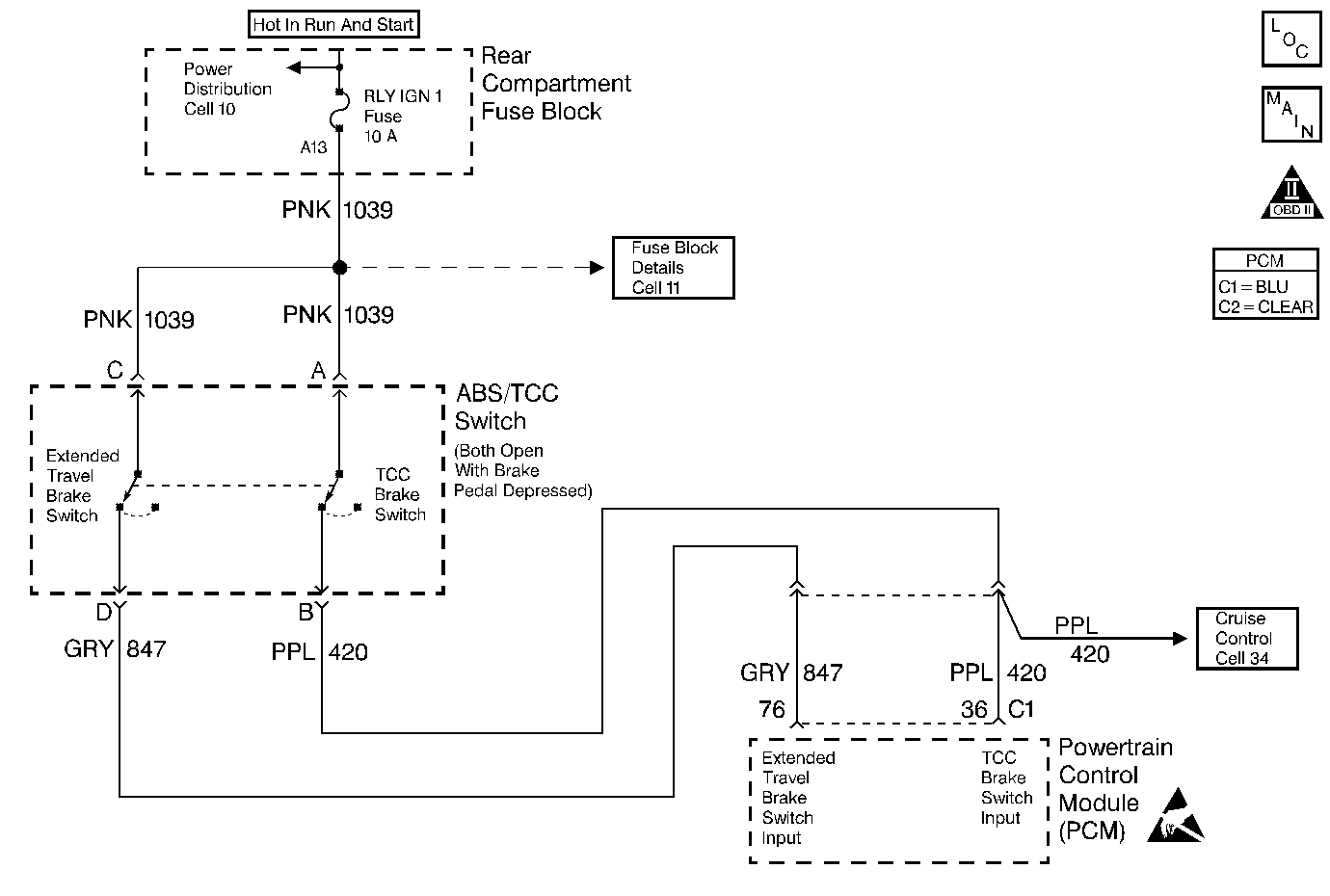
Circuit Description
This diagnostic test functions on the assumption that a sudden decrease in non-drive (rear) wheel speed must be caused by a brake application. Non-drive wheel speed and stop lamp switch status are supplied to the PCM through serial data from the Electronic Brake and Traction Control Module (EBTCM). If there is a 6 MPH or greater decrease of non-drive wheel speed in 0.4 second and a transition of the TCC contacts at the TCC brake switch or stop lamp switch without a transition of the extended travel contacts of the TCC brake, DTC P1575 is set.
Conditions for Running the DTC
| • | DTCs P0703, P1574 and P1604 not set. |
| • | Traction control and antilock brake systems have not failed |
| • | Traction control and antilock brake systems are not active. |
| • | Non-drive wheel speed goes above 20 MPH and then doesnt go below 4 MPH. |
Conditions for Setting the DTC
A 6 MPH or greater decrease in non-drive wheel speed in 0.4 second and TCC brake switch or Stop/BTSI/Cruise brake switch indicating brakes applied and no transition is noticed in the extended travel contacts of the TCC brake switch indicating brakes applied.
Action Taken When the DTC Sets
| • | PCM disables cruise control. |
| • | PCM will set the extended travel brake switch status to not applied. |
| • | The Malfunction Indicator Lamp (MIL) will not illuminate. |
| • | The PCM will command a message to be displayed. |
| • | The PCM may record operating conditions at the time the diagnostic fails. This information will be stored in the Failure Records. |
Conditions for Clearing the Message/DTC
| • | The PCM will turn the message OFF after one run and pass of the diagnostic test. |
| • | A History DTC will clear after forty consecutive warm-up cycles with no failures of any non-emission related diagnostic test. |
| • | A Last Test Failed (current) DTC will clear when the diagnostic runs and does not fail. |
| • | Use a scan tool to clear DTCs. |
| • | Interrupting PCM battery voltage may or may not clear DTCs. This practice is not recommended. Refer to Clearing Diagnostic Trouble Codes in PCM Description and Operation. |
Diagnostic Aids
Use the Failure Records data on the scan tool to help diagnose an intermittent problem. The operating conditions as well as the state of the extended travel brake switch circuit will be stored when the DTC was set.
Step | Action | Value(s) | Yes | No |
|---|---|---|---|---|
1 | Did you perform the Powertrain On-Board Diagnostic (OBD) System Check? | -- | ||
2 |
Does the display indicate Released? | -- | ||
3 | Depress the brake pedal approximately half-way. Does the display indicate Applied? | -- | Go to Diagnostic Aids | |
4 | Disconnect the extended travel brake switch. Does the display indicate Applied? | -- | ||
5 |
Is the voltage more than the value specified? | 0.5 volts | ||
6 | Repair the short to voltage on the Extended Travel Brake Switch Input circuit. Is the repair complete? | -- | -- | |
7 | With a scan tool view the TCC Brake Switch display. Does the display indicate Released? | -- | ||
8 |
Is the voltage the same or more than the value specified? | 10.0 volts | ||
9 | Jumper terminal C to terminal D. Does the display indicate Released? | -- | ||
10 |
Is the voltage the same or more than the value specified? | 10.0 volts | ||
11 | Check fuse A13 (labeled IGN 1). Is the fuse blown? | -- | ||
12 |
Is the voltage the same or more than the value specified? | 10.0 volts | ||
13 |
Is the resistance less than the value specified on any of the terminals? | 100 ohms | ||
14 |
Is the repair complete? | -- | -- | |
15 |
Is the repair/replacement complete? | -- | -- | |
16 | Repair the open in both 1039 circuits. Is the repair complete? | -- | -- | |
17 | Repair the open in CKT 1039 between the extended travel brake switch connector terminal C and the fuse A13 (labeled IGN 1). Is the repair complete? | -- | -- | |
18 | Repair the open in CKT 847. Is the repair complete? | -- | -- | |
19 |
Was terminal contact repaired? | -- | ||
20 | Replace the PCM. Refer to Powertrain Control Module Replacement/Programming . Is the repair complete? | -- | -- | |
21 |
Was an adjustment performed? | -- | ||
22 | Replace the Torque Management brake switch assembly. Is the repair complete? | -- | -- |
