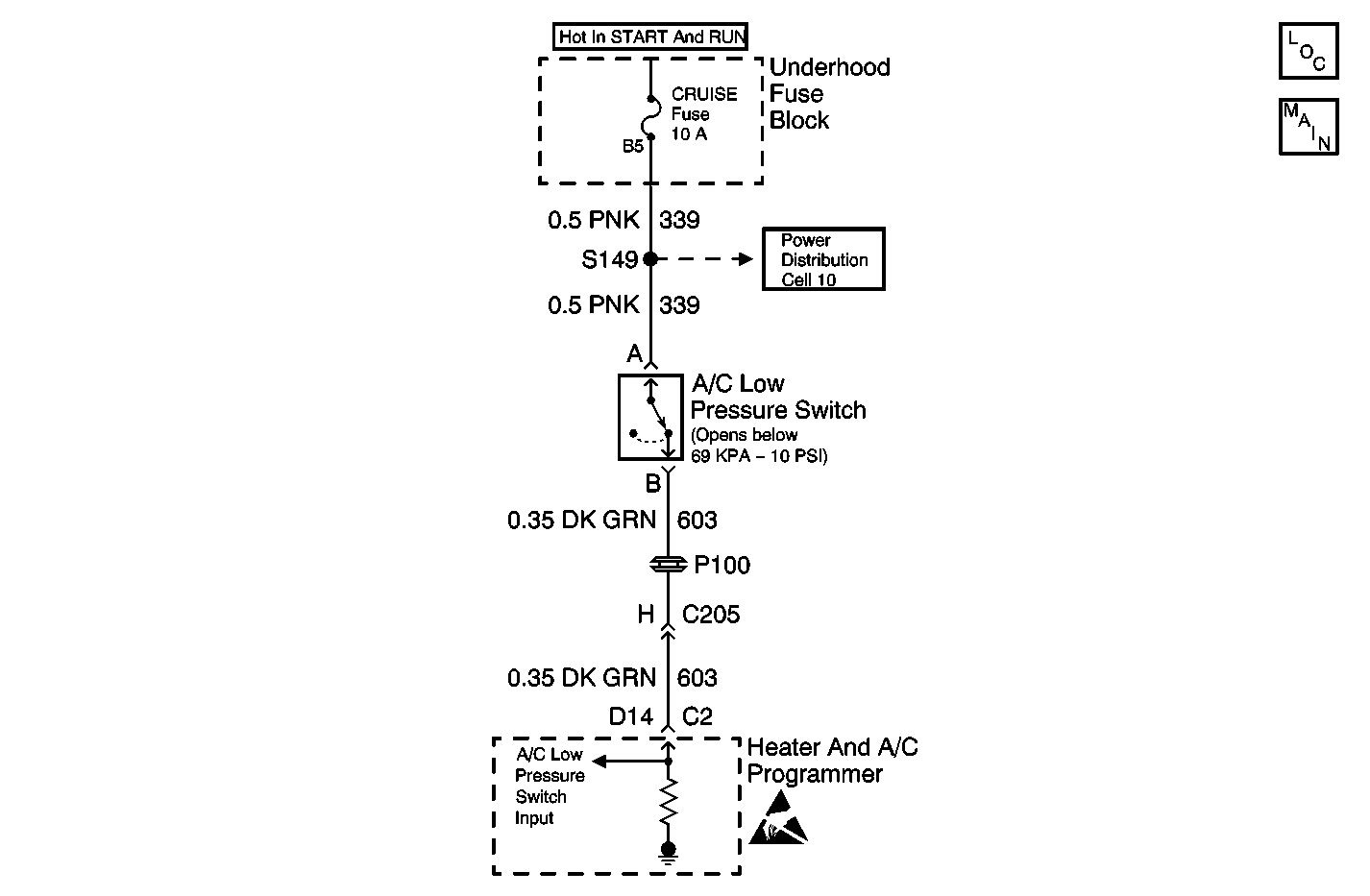
Circuit Description
In the process of controlling the compressor clutch, the heater and A/C programmer monitors certain system inputs for an indication of a low refrigerant charge. The heater and A/C programmer monitors the normally closed low refrigerant pressure switch at pin D14. Inspect the status of the low pressure switch prior to the compressor engagement. If the switch opens, the following actions occur:
| • | The heater and A/C programmer sets DTC B1348. |
| • | The message VERY LOW REFRIGERANT--A/C COMPRESSOR OFF displays on the driver information center (DIC). |
If a DTC B1348 is set, the compressor clutch disengages and remains disengaged until DTC B1348 is cleared.
Failure Conditions
| • | The low refrigerant switch remains open for several minutes. |
| • | The vehicle must be traveling above 48 km/h (30 mph) for at least 30 seconds. This code may not set at idle or in city traffic. |
Action Taken When the DTC Sets
| • | The system disables the compressor until the DTC is cleared. |
| • | The system disables the VERY LOW REFRIGERANT--A/C COMPRESSOR OFF message on the DIC. |
Test Description
-
Perform the Diagnostic System Check before continuing with the diagnosis of this DTC.
-
This test inspects the current state of the low pressure switch.
-
This test inspects the circuits to the low pressure switch.
-
This test inspects for a restriction in the refrigerant system.
-
This test inspects the HVAC refrigerant system pressure.
Step | Action | Value(s) | Yes | No |
|---|---|---|---|---|
Did you perform the Diagnostic System Check? | -- | Go to Step 2 | Go to Diagnostic System Check | |
Is the status OPEN? | -- | Go to Step 3 | Go to Step 4 | |
Does the status remain OPEN (switches closed)? | -- | Go to Step 5 | Go to Step 12 | |
Is the calculated and gauge pressure within the specified value? | 10 % | Go to Step 8 | Go to Step 9 | |
5 | Measure the voltage from the jumper to ground. Refer to Measuring Voltage in Wiring Systems. Is the voltage equal to or greater than the specified value? | 8 V | Go to Step 6 | Go to Step 7 |
6 |
Did you complete the repair? | -- | Go to Step 15 | -- |
7 | Repair the open or short to ground on switch feed 339 or replace the blown fuse. Refer to Wiring Repairs in Wirning Systems. Did you complete the repair? | -- | Go to Step 15 | -- |
8 |
Does the display cycle from HI to LO? | -- | Go to Step 10 | Go to Step 11 |
9 | Inspect for a restriction within the refrigerant system between the temperature sensor and the service connection gauge that did not agree. Did you complete the repair? | -- | Go to Step 15 | -- |
10 |
Did you complete the repair? | -- | Go to Step 15 | -- |
11 | Replace the low pressure switch. Refer to Temperature Sensor Replacement - Low Side . Did you complete the repair? | -- | Go to Step 15 | -- |
Is the pressure above the specified value? | 10 psi | Go to Step 13 | Go to Step 14 | |
13 |
Did you complete the repair? | -- | Go to Step 15 | -- |
14 |
Did you complete the repair? | -- | Go to Step 15 | -- |
15 |
Did you complete the repair? | -- | Go to Diagnostic System Check | -- |
