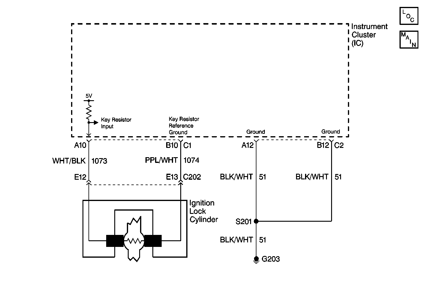
Circuit Description
When an ignition key is inserted into the ignition switch, the terminals located in the steering column lock cylinder contact the key pellet resistor on the ignition key. The IPC measures the resistance of the key pellet and then measures the resistance to the one stored in the IPCs memory.
Conditions for Setting the DTC
The DTC will set under the following conditions:
| • | B2710 indicates that an open or zero resistance value was measured from the key pellet prior to obtaining a valid resistance measurement. |
| • | B2711 indicates that an open or zero resistance value was measured from the key pellet following a valid resistance measurement. |
Action Taken When the DTC Sets
| • | When DTC B2710 is set current the IPC displays the STARTING DISABLED, REMOVE IGNITION KEY message on the driver message center and prevents the vehicle from starting. |
| • | When DTC B2711 is set current the IPC displays the THEFT SYSTEM PROBLEM, CAR MAY NOT RESTART message on the driver message center and allows the vehicle to continue to run. |
Diagnostic Aids
Inspect for intermittent opens, shorts, or loose connections in CKT 1073 (WHT/BLK) or CKT 1074 (PPL/WHT).
Step | Action | Value(s) | Yes | No | ||||
|---|---|---|---|---|---|---|---|---|
1 | Did you perform the IC Diagnostic System Check? | -- | Go to Step 2 | |||||
2 |
Is the resistance less than the specified value? | 20ohms | Go to Step 3 | Go to Step 4 | ||||
3 | Remove the ignition key from the ignition switch. Is the resistance greater than the specified value? | 10k ohms | Go to Step 12 | Go to Step 13 | ||||
4 | Is the resistance greater than the specified value? | 11.8k ohms | Go to Step 5 | Go to Step 6 | ||||
5 | Place another ignition key in the ignition switch. Is the resistance less than the specified value? | 11.8k ohms | Go to Step 13 | Go to Step 12 | ||||
6 |
Is the resistance less than the specified value? | 5ohms | Go to Step 7 | Go to Step 8 | ||||
7 | Repair the short in the following circuits:
Refer to Wiring Repairs in Wiring Systems. Did you complete the repair? | -- | -- | |||||
8 | Connect the DMM between the IPC connector C1 terminal A10 and ground. Is the resistance less than the specified value? | 5ohms | Go to Step 9 | Go to Step 10 | ||||
9 | Repair the short to ground in CKT 1073 (WHT/BLK). Refer to Wiring Repairs in Wiring System Did you complete the repair? | -- | -- | |||||
10 | Connect the DMM between the IPC connector C1 terminal B10 and ground. Is the resistance less than the specified value? | 5ohms | Go to Step 11 | Go to Step 14 | ||||
11 | Repair the short to ground in CKT 1074 (PPL/WHT). Refer to Wiring Repairs in Wiring System Did you complete the repair? | -- | -- | |||||
12 | Replace the ignition key. Refer to Cutting Keys and Key Identification in General Information. Did you complete the repair? | -- | -- | |||||
13 | Replace the steering column lock cylinder. Refer to Steerin Column Lock Cylinder Replacement in Tilt Steering Column Unit Repair. Did you complete the repair? | -- | -- | |||||
14 | Replace the IPC. Refer to Instrument Cluster Replacement . Did you complete the repair? | -- | -- |
