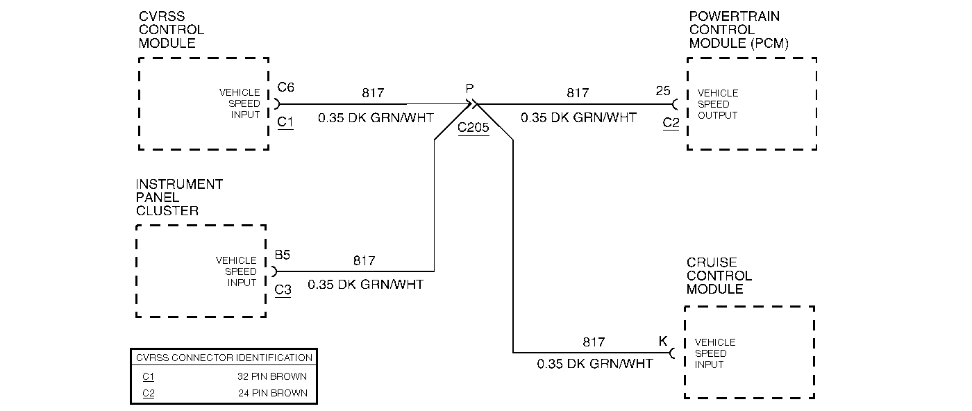
Circuit Description
The CVRSS control module receives a vehicle speed signal from the Powertrain Control Module (PCM) via a discrete line and also receives vehicle speed data via the Class 2 communication link. The CVRSS module compares the vehicle speed received over Class 2 to the vehicle speed obtained directly from the PCM.
Conditions for Setting the DTC
The DTC is set when the vehicle speed received over Class 2 is greater than 20 MPH while the vehicle speed obtained from the PCM is less than 3 MPH continuously for 10 seconds.
The DTC turns HISTORY when the CVRSS control module senses the vehicle speed signal from the PCM is greater than 5 MPH.
Action Taken When the DTC Sets
| • | The CVRSS system will use only the Class 2 vehicle speed data. Otherwise, the CVRSS system will operate normally. |
| • | The SERVICE RIDE CONTROL message will be displayed. |
Conditions for Clearing the MIL/DTC
| • | Use the scan tool. |
| • | Use the On-Board diagnostic CLEAR RSS CODES feature. |
Test Description
Important:
• Do not backprobe the sensors, actuators, or any sealed connectors. • When all the diagnostics and repairs are complete, clear the DTCs
and verify the operation.
The number(s) below refer to the step number(s) on the diagnostic table.
-
This step checks to see if the related PCM DTC is set.
-
This step checks for an open circuit condition in circuit 817.
Step | Action | Value(s) | Yes | No |
|---|---|---|---|---|
1 | Was the CVRSS System Check performed? | -- | Go to Step 2 | |
Is DTC P1642 set? | -- | Go to Step 3 | ||
3 |
Was there continuity? | -- | Go to Step 4 | Go to Step 5 |
Check for an intermittent open circuit condition in circuit 817. Refer to Intermittents and Poor Connections . Was an intermittent open circuit condition found? | -- | Go to Step 5 | Go to Step 6 | |
5 | Repair the intermittent open circuit condition in circuit 817. Is the repair complete? | -- | -- | |
6 |
Is DTC C1743 set? | -- | Go to Step 7 | |
7 |
Important: The controller must be calibrated. Is the CVRSS control module calibrated? | -- | -- |
