DTC B2101 Recline Aft Switch Failed Eldorado

Circuit Description
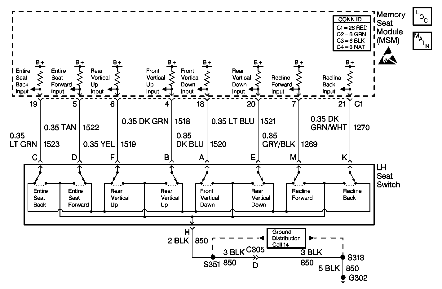
The memory seat module (MSM) receives an input from the left seat switch recline switch when the switch is actuated. When the recline switch is operated in the back direction, battery positive voltage (B+) is supplied to the MSM recliner back input via CKT 1270 (DK GRN/WHT). The MSM recognizes the input and moves the seat back in the back direction.
Conditions for Setting the DTC
| • | When the recline back switch is active for 30 seconds after motion has ceased, the switch is considered shorted and the DTC sets. |
| • | If the recline position sensor DTC B2115 is current and the recline back switch is active for 30 seconds, the switch is considered shorted and the DTC will set. |
| • | DTC B2101 sets only if DTC B1982 MSM or DTC B1983 MSM is not current. |
Action Taken When the DTC Sets
| • | The MSM does not recline the seat back in the back direction. |
| • | The MSM continues responding to valid inputs from the other manual switches. |
| • | All memory recall function commands are ignored for all directions. |
Conditions for Clearing the DTC
| • | The MSM sees that the recline back switch is no longer active. |
| • | Use the on-boards clearing DTCs feature. |
| • | Use a scan tool. |
Test Description
The numbers below refer to the step numbers on the diagnostic table:
-
Perform the entire Power Seat Systems Diagnostic System Check before continuing with the diagnosis of this DTC.
-
This step determines whether a switch is stuck or whether the wiring input to the memory seat module (MSM) has a short to battery positive voltage (B+). DTC B2101 will set again if a short in the wiring or an internal MSM condition is present. DTC B2101 will not set again if a switch is stuck because the switch has been disconnected from the memory seat module (MSM) input.
-
This step determines whether the input wiring to the MSM has a short to battery positive voltage (B+).
-
Clear all DTCs after the repair procedure is complete.
Step | Action | Value(s) | Yes | No |
|---|---|---|---|---|
Was the entire Power Seat Systems Diagnostic System Check performed? | -- | Go to Step 2 | ||
After 30 seconds, does DTC B2101 reset? | -- | Go to Step 3 | Go to Step 5 | |
Is the voltage within the specified range? | 10-15 V | Go to Step 6 | Go to Step 4 | |
4 | Replace the memory seat module (MSM). Refer to Memory Seat Control Module Replacement . Is the MSM replacement complete? | -- | Go to Step 7 | -- |
5 | Replace the left seat switch. Refer to Power Seat Switch Replacement . Is the left seat switch replacement complete? | -- | Go to Step 7 | -- |
6 | Repair the short to battery positive voltage (B+) in CKT 1270 (DK GRN/WHT). Refer to Wiring Repairs in Wiring Systems. Is the circuit repair complete? | -- | Go to Step 7 | -- |
Are all DTCs cleared? | -- | -- |
DTC B2101 Recline Aft Switch Failed DeVille

Circuit Description
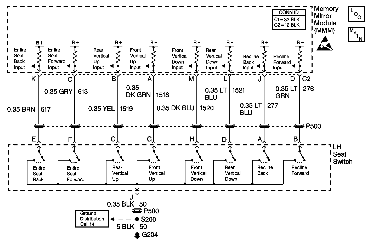
The memory seat module (MSM) receives an input from the left seat switch recline switch when the switch is actuated. When the recline switch is operated in the back direction, battery positive voltage (B+) is supplied to the MSM recliner back input via CKT 277 (LT BLU). The MSM recognizes the input and moves the seat back in the back direction.
Conditions for Setting the DTC
| • | When the recline back switch is active for 30 seconds after motion has ceased, the switch is considered shorted and the DTC sets. |
| • | If the recline position sensor DTC B2115 is current and the recline back switch is active for 30 seconds, the switch is considered shorted and the DTC sets. |
| • | DTC B2101 sets only if DTC B1982 MSM or DTC B1983 MSM is not current. |
Action Taken When the DTC Sets
| • | The MSM does not recline the seat back in the back direction. |
| • | The MSM continues responding to valid inputs from the other manual switches. |
| • | All memory recall function commands are ignored for all directions. |
Conditions for Clearing the DTC
| • | The MSM sees that the recline back switch is no longer active. |
| • | Use the on-boards clearing DTCs feature. |
| • | Use a scan tool. |
Test Description
The numbers below refer to the step numbers on the diagnostic table:
-
Perform the entire Power Seat Systems Diagnostic System Check before continuing with the diagnosis of this DTC.
-
This step determines whether there a switch is stuck or whether the wiring input to the memory seat module (MSM) has a short to battery positive voltage (B+). DTC B2101 will set again a short in the wiring or an internal MSM condition is present. DTC B2101 will not set again if a switch is stuck because the switch has been disconnected from the MSM input.
-
This step determines whether the input wiring to the MSM has a short to battery positive voltage (B+).
-
Clear all DTCs after the repair procedure is complete.
Step | Action | Value(s) | Yes | No |
|---|---|---|---|---|
Was the entire Power Seat Systems Diagnostic System Check performed? | -- | Go to Step 2 | ||
After 30 seconds, does DTC B2101 reset? | -- | Go to Step 3 | Go to Step 5 | |
Is the voltage within the specified range? | 10-15 V | Go to Step 6 | Go to Step 4 | |
4 | Replace the memory seat module (MSM). Refer to Memory Seat Control Module Replacement . Is the MSM replacement complete? | -- | Go to Step 7 | -- |
5 | Replace the left seat switch. Refer to Power Seat Switch Replacement . Is the left seat switch replacement complete? | -- | Go to Step 7 | -- |
6 | Repair the short to battery positive voltage (B+) in CKT 277 (LT BLU). Refer to Wiring Repairs in Wiring Systems. Is the circuit repair complete? | -- | Go to Step 7 | -- |
Are all DTCs cleared? | -- | -- |
