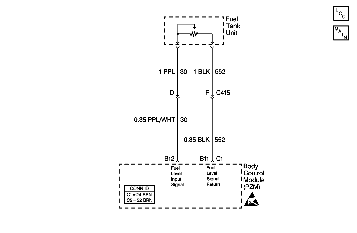
Circuit Description
The body control module (PZM) determines the fuel level by calculating the resistance of the fuel level sender circuit. The PZM then sends the fuel level over the class 2 serial data line to the modules that require the data.
Conditions for Setting the DTC
| • | DTC B0532 does not set if DTCs B1982 or B1983 are current. |
| • | The resistance across connector C1 terminals B12 and B11 is out of range. |
Action Taken When the DTC Sets
| • | The PZM sends a class 2 message to the PCM that the fuel level is too low. |
| • | The PZM sets B0532 as current. |
Conditions for Clearing the DTC
| • | The resistance across connector C1 terminals B12 and B11 is within range. The DTC changes to history. |
| • | The DTC clears after 50 consecutive ignition cycles if the condition no longer is present. |
Step | Action | Value(s) | Yes | No |
|---|---|---|---|---|
1 | Was the Body Control Module Diagnostic System Check performed? | -- | Go to Step 2 | |
2 |
Is the DTC still present? | -- | Go to Step 3 | |
3 |
Is resistance within the specified range? | 40-250 ohms | Go to Step 4 | Go to Step 5 |
4 | Replace the PZM. Refer to Body Control Module Replacement . Is the repair complete? | -- | Go to Step 10 | -- |
5 |
Is the resistance within the specified range? | 5 ohms | Go to Step 6 | Go to Step 7 |
6 | Measure the resistance from the PZM connector C1 terminal B12 to ground. Is the resistance the specified value? | Infinite | Go to Step 9 | Go to Step 8 |
7 | Repair the open in CKT 30 (PPL/WHT) or CKT 651 (BLK). Refer to Wiring Repairs in Wiring Systems. Is the repair complete? | -- | Go to Step 10 | -- |
8 | Repair the short to ground in CKT 30 (PPL/WHT) or CKT 552 (BLK). Refer to Wiring Repairs in Wiring Systems. Is the repair complete? | -- | Go to Step 10 | -- |
9 | Replace the fuel tank unit. Is the repair complete? | -- | Go to Step 10 | -- |
10 |
Is the repair complete? | -- | -- |
