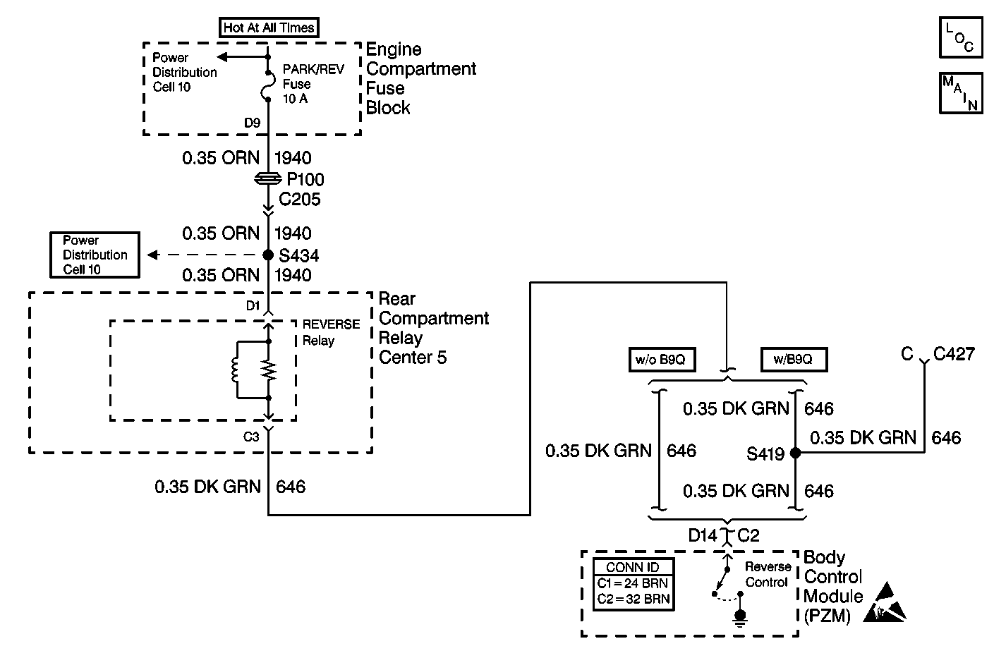
Circuit Description
When the body control module (PZM) receives a class 2 serial data message that the transaxle is in reverse, the PZM energizes the reverse lamp relay and the backup lamps are turned on. When the PZM has not commanded the backup lamps on, the voltage at connector C2 terminal D14 is measured every 1000 ms.
Conditions for Setting the DTC
The PZM determines the voltage at connector C2 terminal D14 is approximately equal to ground.
Actions Taken When the DTC Sets
The PZM continues to command the state requested until the state is achieved or until the request changes.
Conditions for Clearing the DTC
The PZM determines the voltage at connector C2 terminal D14 is greater than ground for at least 1 monitoring cycle.
Troubleshooting Hints
Test CKT 646 (DK GRN) for a short to ground.
Step | Action | Value(s) | Yes | No |
|---|---|---|---|---|
1 | Was the Body Control Module Diagnostic System Check performed? | -- | Go to Step 2 | |
2 |
Is the resistance within the specified range? | 0-5 ohms | Go to Step 3 | Go to Step 4 |
3 | Repair the short to ground in CKT 646 (DK GRN). Is the repair complete? | -- | -- | |
4 | Replace the PZM. Refer to Body Control Module Replacement . Is the repair complete? | -- | -- |
