Stabilizer Shaft Replacement FE1, FE3
Tools Required
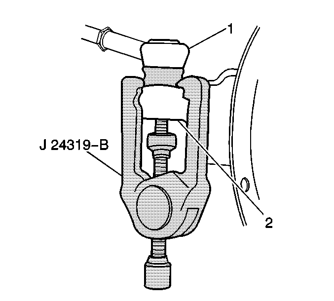
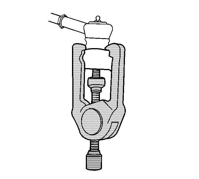
J 24319-B Universal Steering Linkage Puller
Removal Procedure
- Raise the vehicle and support by the frame allowing the control arms to hang free. Refer to Lifting and Jacking the Vehicle in General Information.
- Remove the wheels and tires. Refer to Tire and Wheel Removal and Installation in Tires and Wheels.
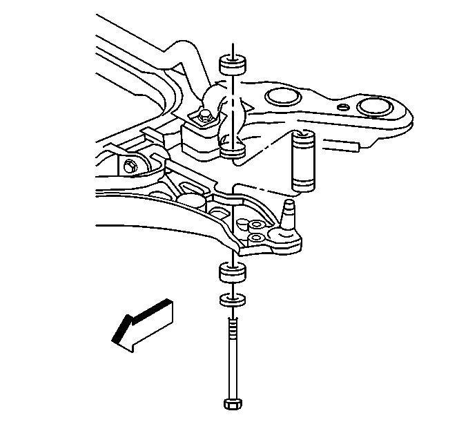
- Remove the stabilizer link bolts.
- Remove the stabilizer shaft brackets.
- Remove the tie rod end from steering knuckle using J 24319-B .
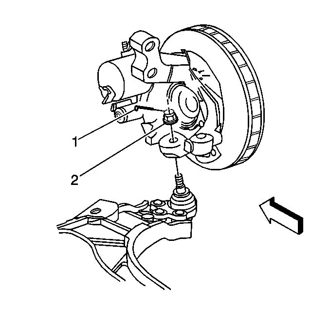
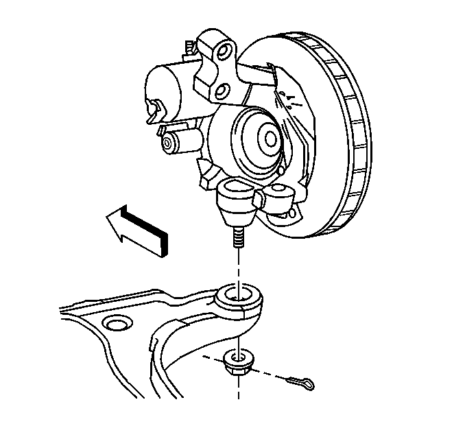
- Separate the ball joint. Refer to Lower Control Arm Ball Joint Replacement .
- Turn the right steering knuckle to the left, and guide the stabilizer shaft half out the right side of the vehicle in an upward direction, then remove the stabilizer shaft out the bottom center of the vehicle.

Installation Procedure
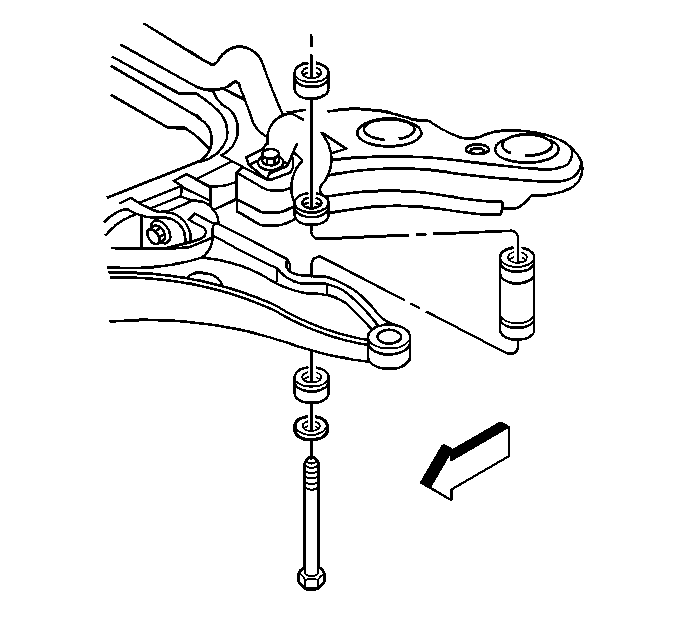
- Install the stabilizer shaft into position.
- Install the ball joint to steering knuckle. Refer to Lower Control Arm Ball Joint Replacement .
- Install the ball joint nut (2).
- Loosely install the right and left stabilizer shaft insulators, brackets and bolts.
- Loosely install the stabilizer link insulators, washers, nut, and bolt.
- Install the tie rod to steering knuckle.
- Install the cotter pin in tie rod end.
- Install the front wheels and tires. Refer to Tire and Wheel Removal and Installation in Tires and Wheels.
- Lower the vehicle.
Notice: Use the correct fastener in the correct location. Replacement fasteners must be the correct part number for that application. Fasteners requiring replacement or fasteners requiring the use of thread locking compound or sealant are identified in the service procedure. Do not use paints, lubricants, or corrosion inhibitors on fasteners or fastener joint surfaces unless specified. These coatings affect fastener torque and joint clamping force and may damage the fastener. Use the correct tightening sequence and specifications when installing fasteners in order to avoid damage to parts and systems.
Tighten
Tighten the ball joint nut to 30 N·m (22 lb ft).
Then tighten an additional 200 degrees. Do not tighten any more than 60 degrees
additional to install cotter pin. Do not loosen to install cotter pin.
Tighten
| • | Tighten the stabilizer bracket bolts to 33 N·m (24 lb ft). |
| • | Tighten the stabilizer link nut to 17 N·m (13 lb ft). |
| • | Tighten the tie rod end to knuckle nut to 10 N·m (88 lb in) plus an additional 180 - 300 degrees (3 - 5 flats). For cotter pin alignment tighten up to, but do not exceed 60 degrees additional rotation. Do not back off nut for cotter pin insertion. |
Tighten
Tighten the wheel nuts to 125 N·m (80 lb ft).
Stabilizer Shaft Replacement FE7
Tools Required
J 24319-B Universal Steering Linkage Puller
Removal Procedure
- Raise and support the vehicle. Refer to Lifting and Jacking the Vehicle in General Information.
- Remove the tire and wheels. Refer to Tire and Wheel Removal and Installation in Tires and Wheels.
- Remove the stabilizer links. Refer to Stabilizer Shaft Link Replacement .
- Remove the stabilizer shaft bracket bolts.
- Remove the stabilizer shaft brackets.
- Remove the outer tie rod retaining nuts.
- Using J 24319-B disconnect the outer tie rod from the steering knuckle.
- Separate the ball joint. Refer to Lower Control Arm Ball Joint Replacement .
- Turn the right steering knuckle to the left, and guide the stabilizer shaft half out the right side of the vehicle in an upward direction, then remove the stabilizer shaft out the bottom center of the vehicle.

Installation Procedure
- Install the stabilizer shaft to the vehicle.
- Install the ball joint to steering knuckle. Refer to Lower Control Arm Ball Joint Replacement .
- Install the ball joint retaining nut.
- Loosely install the right and left stabilizer shaft insulators, brackets and bolts.
- Loosely install the stabilizer link insulators, washers, nut, and bolt.
- Install the tie rod to steering knuckle.
- Install the cotter pin in tie rod ends.
- Install the front wheels and tires. Refer to Tire and Wheel Removal and Installation in General Information.
- Lower the vehicle.
Notice: Use the correct fastener in the correct location. Replacement fasteners must be the correct part number for that application. Fasteners requiring replacement or fasteners requiring the use of thread locking compound or sealant are identified in the service procedure. Do not use paints, lubricants, or corrosion inhibitors on fasteners or fastener joint surfaces unless specified. These coatings affect fastener torque and joint clamping force and may damage the fastener. Use the correct tightening sequence and specifications when installing fasteners in order to avoid damage to parts and systems.
Tighten
Tighten the ball joint retaining nut to 30 N·m (22 lb ft).
Then tighten the nut an additional 190 degrees.
Tighten
| • | Tighten the stabilizer bracket bolts to 67 N·m (49 lb ft). |
| • | Tighten the stabilizer link nut to 23 N·m (17 lb ft). |
| • | Tighten the tie rod end to knuckle nut to 30 N·m (22 lb in) plus an additional 200 degrees. |
