Removal Procedure
- Place the vehicle on a flat surface
- Remove air cleaner assembly. Refer to Air Cleaner Assembly Replacement in Engine Controls.
- Remove the master cylinder. Refer to Master Cylinder Replacement .
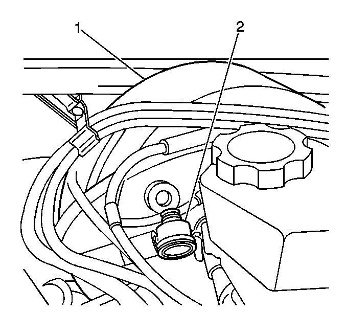
- Remove the vacuum hose (2) from the vacuum booster.
- Set the parking brake.
- in Caution and Notices.
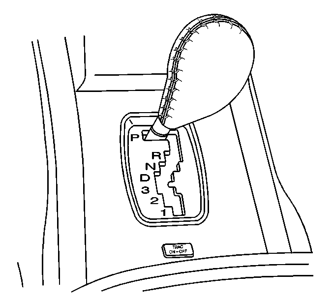
- To allow access for the removal of the brake booster, position gearshift lever into lowest gear.
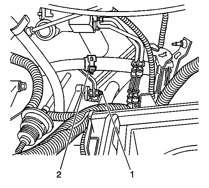
- Remove retaining nut from coolant tube (1) Position coolant tube (2) out of way to allow access for removal of brake booster
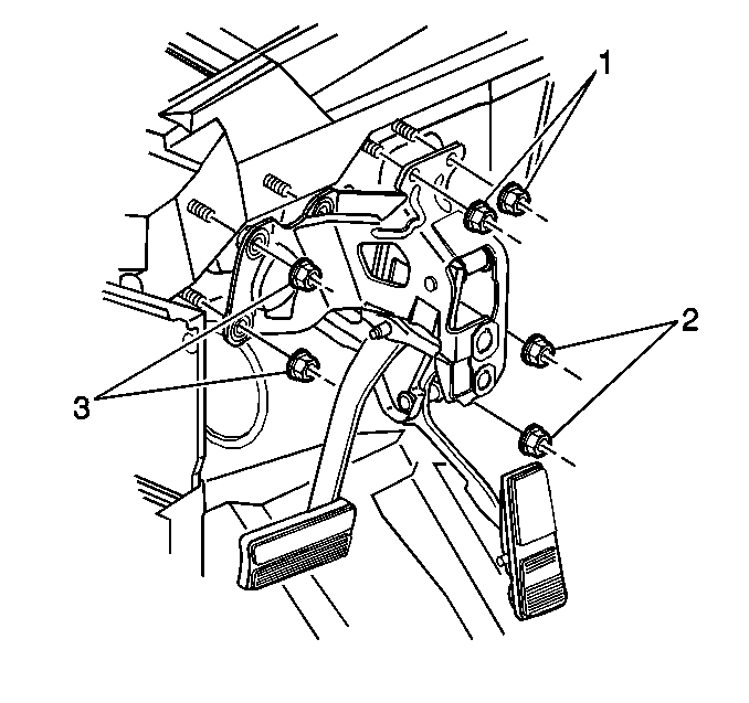
- Remove the booster attaching nuts (1,2,3,) from the brake pedal assembly.
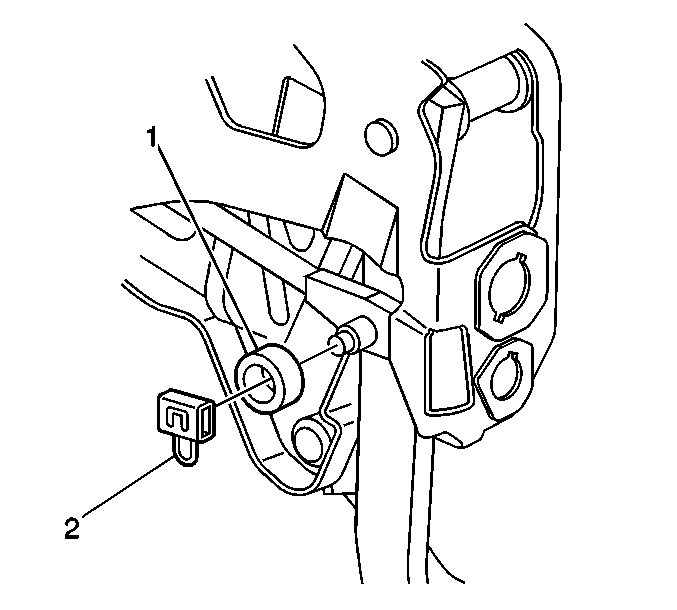
- Remove the retaining clip (2 ) from booster pushrod. Tilt the entire booster slightly to work pushrod off the pedal clevis pin without putting undue side pressure on the pushrod.
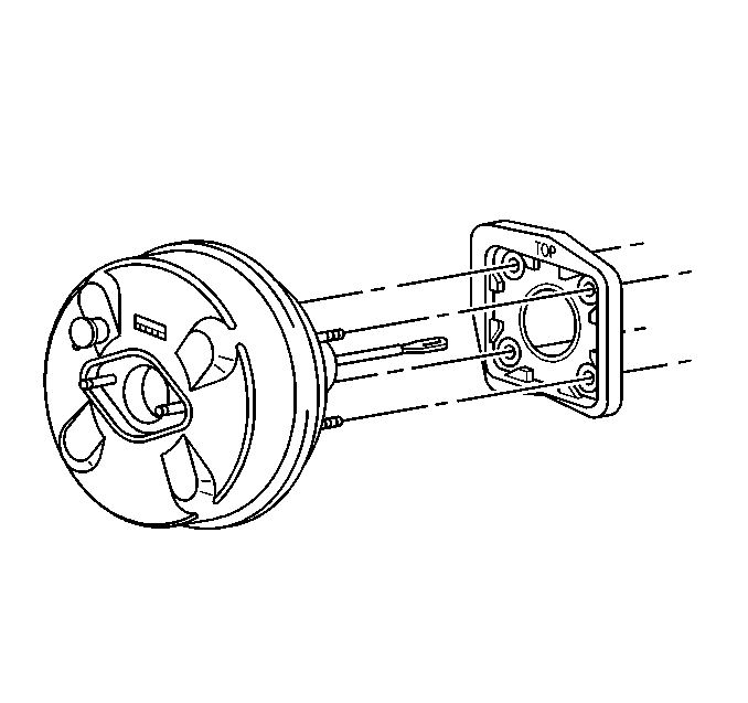
- Remove the booster from the vehicle.
- Remove the gasket.
Caution: Chock the wheels to prevent the vehicle from moving. Failure to chock the wheels can cause personal injury when the electrical system is repaired.
Installation Procedure
- Install the gasket to booster.
- Install the booster to the vehicle.
- Install the booster pushrod to the brake pedal. Tilt the entire booster slightly to work pushrod on the pedal clevis pin (2) without putting undue side pressure on the pushrod.
- Install the booster attaching nuts (1,2,3,) onto the booster studs.
- Position coolant tube on the retaining stud (2) install the retaining nut (1).
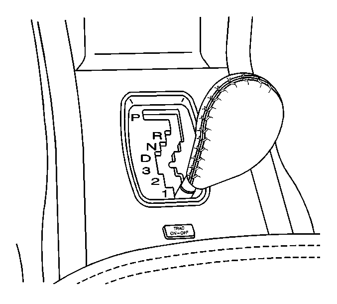
- Position the gearshift lever into park
- Install the booster vacuum hose (2) in the vacuum booster.
- Install the Master cylinder. Refer to Master Cylinder Replacement .
- Install the air cleaner assembly. Refer to Air Cleaner Assembly Replacement in Engine Controls.
- Unblock the wheels.
- Release the parking brake.


Notice: Use the correct fastener in the correct location. Replacement fasteners must be the correct part number for that application. Fasteners requiring replacement or fasteners requiring the use of thread locking compound or sealant are identified in the service procedure. Do not use paints, lubricants, or corrosion inhibitors on fasteners or fastener joint surfaces unless specified. These coatings affect fastener torque and joint clamping force and may damage the fastener. Use the correct tightening sequence and specifications when installing fasteners in order to avoid damage to parts and systems.
Tighten
Tighten the brake pedal to booster stud nuts to 32 N·m
(24 lb ft).

Tighten
Tighten the coolant tube retaining nuts to 6 N·m (53 lb in).
