COOL AIR DEFROST /SIDE WINDOW DEFOG(DIAG/REPL SPLITTER WALL)

SUBJECT: COOL AIR FROM DEFROST AND SIDE WINDOW DEFOG OUTLETS
MODELS AFFECTED: 1992 ELDORADOS AND SEVILLES
Some vehicle climate control systems on 1992 Eldorados and Sevilles may exhibit cool air from the defrost and side window defog outlets when operating in "AUTO" settings which call for heat or for defog mode. This condition may be described as causing cold hands, cold face, and/or cold left knee and is most likely to occur after a 40 to 45 minute drive as the interior vehicle temperatures begin to reach the desired setting and the system begins to stabilize.
As the ECC system begins to stabilize while in the heat mode, the temperature of the heated air delivered to the ducts begins to lower to help maintain the requested interior temperature. The system uses many hardware and software components to mix and deliver the air to the proper ducts to maintain comfort. The following components may contribute to the cause of this condition:
A. Inside Air Temp Sensor-may not be seated and/or sealed properly allowing heated air from the I/P interior to be drawn into the sensor producing a false sensor reading.
B. Aspirator Hose and Aspirator - hose may be kinked or damaged or aspirator may not be properly seated to module preventing the necessary air flow from the interior over the sensor.
C. Air Mix Valve/Door - may be misadjusted preventing the proper mix of heated and cooled air from entering the ducts. (Refer to Section 1-B of the Service Information Manual for proper air mix valve adjustment.)
IMPORTANT: It is necessary to inspect each of these items to assure a complete and satisfactory correction.
If after inspection of the above items no problem is found, then the problem may be caused by the improper mixing of the air by the baffles contained in the HVAC module. To correct this condition replace the splitter wall within the module with a modified part, P/N 52465553, by completing the following procedure.
NOTICE: To prevent short circuit damage when removing or installing certain electrical units, disconnect the negative (-) battery cable and turn ignition switch to "OFF" position.
CAUTION:
The procedure that follows must be followed in the order listed to temporarily disable the Supplemental Inflatable Restraint (SIR) system and prevent false diagnostic codes from setting. Failure to follow procedures could result in possible air bag deployment, personal injury, or otherwise unneeded SIR system repairs.
NOTICE: The DERM can maintain sufficient voltage to cause a deployment for up to ten minutes after the ignition switch is turned off or battery is disconnected.
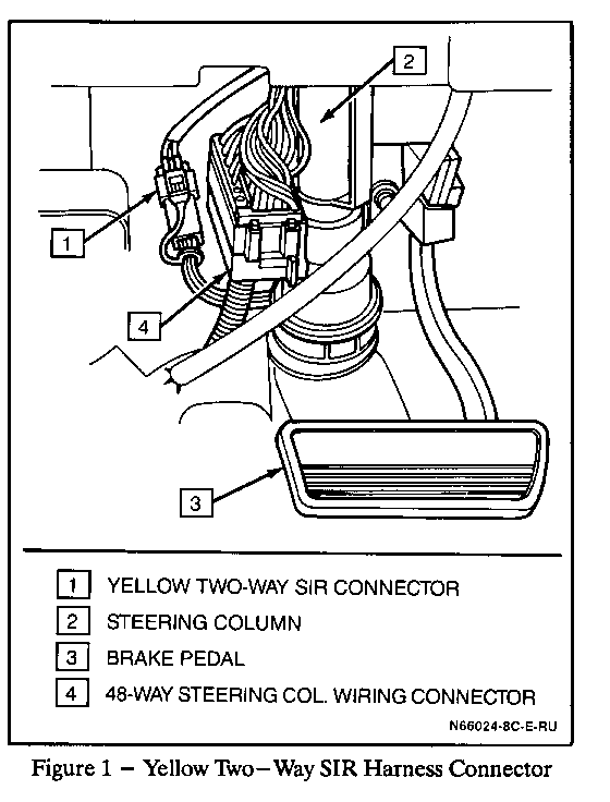
Disable SIR System (refer to Figure 1):
1. Remove SIR fuse A11 from engine compartment fuse panel.
2. Remove two screws and courtesy lamp from left side sound insulator and remove insulator.
3. Remove Connector Position Assurance (CPA) and yellow two-way connector at the base of the steering column.
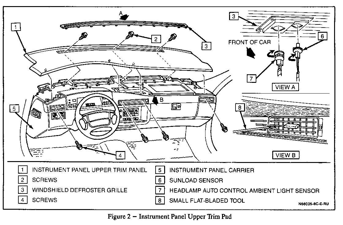
Remove I/P Upper Trim Panel (refer to Figure 2): ------------------------------------------------ 4. Remove defroster grill using a small, flat-bladed tool and prying upward.
5. Disconnect sunload sensor and headlamp auto control sensor from defroster grill.
6. Remove three screws retaining upper trim panel through defroster grill opening.
7. Remove A/C vents from front of I/P by releasing tab on each side from inside vent and pulling out.
8. Remove four screws that hold upper trim panel through vent openings and remove panel.
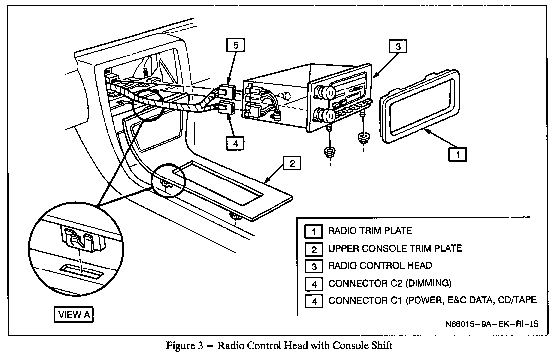
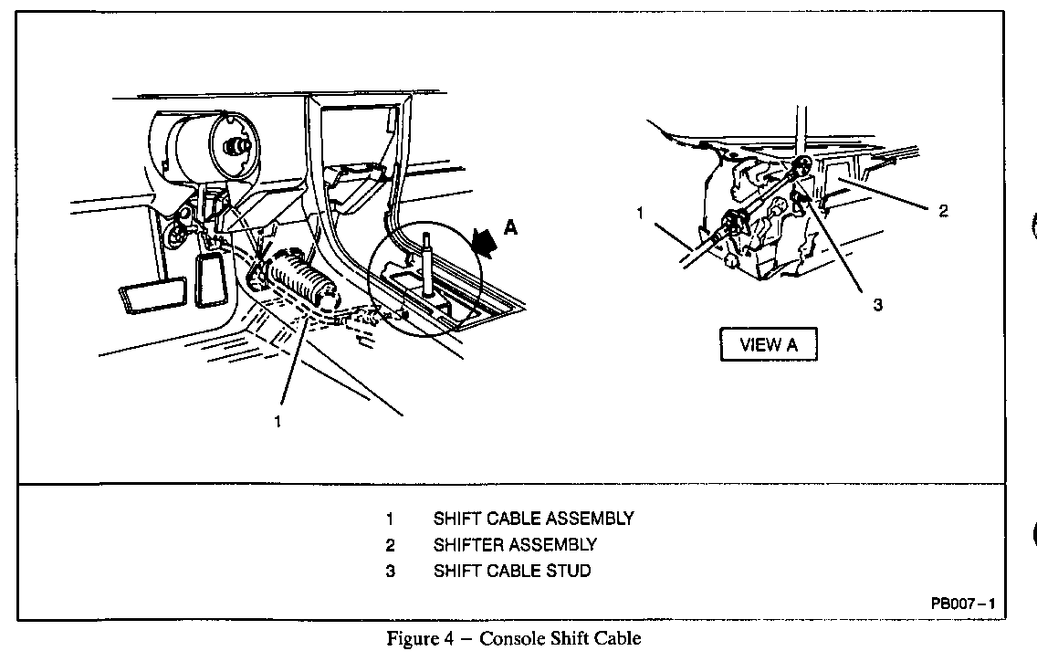
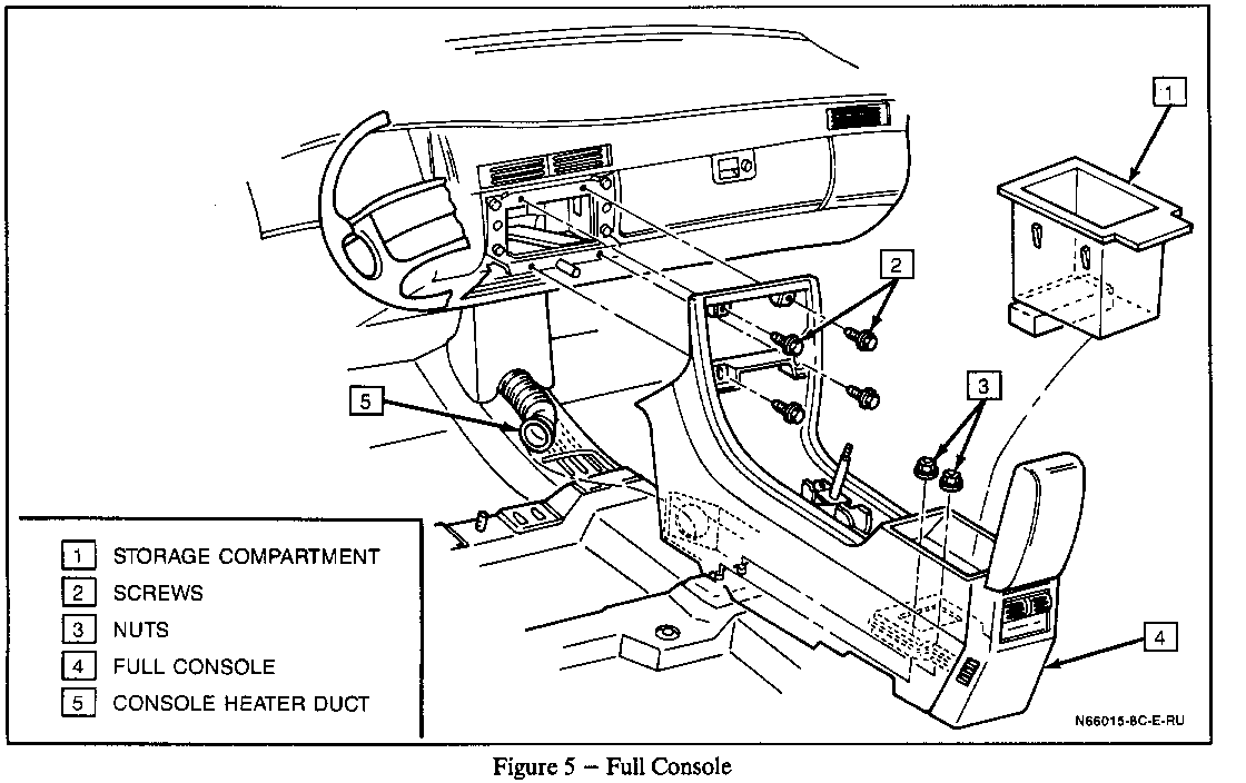
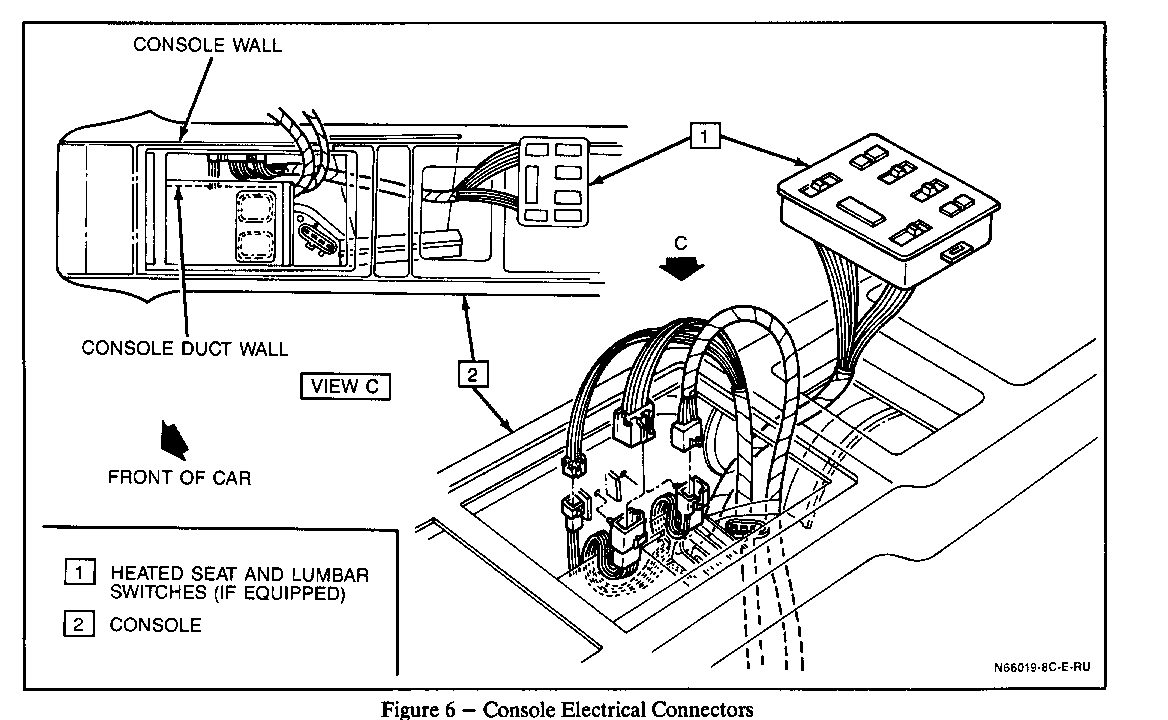
Remove Full Console Assembly (if vehicle is so equipped [if mini-console, move to step 27]) (refer to Figures 3 through 6): ----------------------------------------------------------------------------- 9. Remove radio trim plate.
10. Remove console trim plate by gently pulling up and out to disengage clips.
11. Disconnect cigar lighter connector.
12. Remove two nuts from bottom of radio control head. Remove control head from I/P by sliding rearward.
13. Disconnect radio connectors.
14. Remove four screws retaining console to instrument panel. Refer to Figure 5.
15. Disconnect park lock and shift cable from shifter base to allow for removal of two screws at base of shifter.
16. Remove two screws at base of shifter.
17. Disconnect shift cable from shifter assembly.
18. Disconnect park lock cable from shifter assembly.
19. Disconnect BTSI solenoid electrical connector from solenoid (on shifter assembly).
20. Disengage PRNDL illumination lamp from gear selector trim plate.
21. Disconnect vacuum lines at console assembly.
22. Remove shifter assembly from console.
23. Remove console storage compartment by pulling up and out.
24. Remove two nuts through storage compartment opening that retain console to floor.
25. Disconnect console blower air supply duct by turning to release.
26. Slide console up and disconnect electrical connectors. Slide console rearward in car to provide clearance to remove I/P.
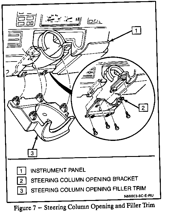
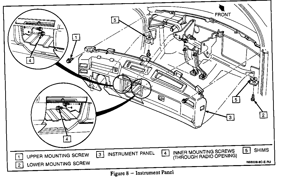
Remove Instrument Panel (refer to Figures 7 and 8):
27. Remove right side sound insulator.
28. Remove steering column opening filler trim by grasping at the front and rear edges and pulling downward.
29. Remove four screws holding steering column opening bracket and remove bracket.
30. Remove four bolts retaining steering column and carefully lower column. Allow column to rest on driver's seat. It is not necessary to disconnect intermediate shaft or to remove column from car.
31. Remove two bolts from hood latch release and disconnect from I/P.
32. Remove eight bolts retaining instrument panel, disconnect the various electrical connectors, and with the help of another technician remove the instrument panel from the vehicle.
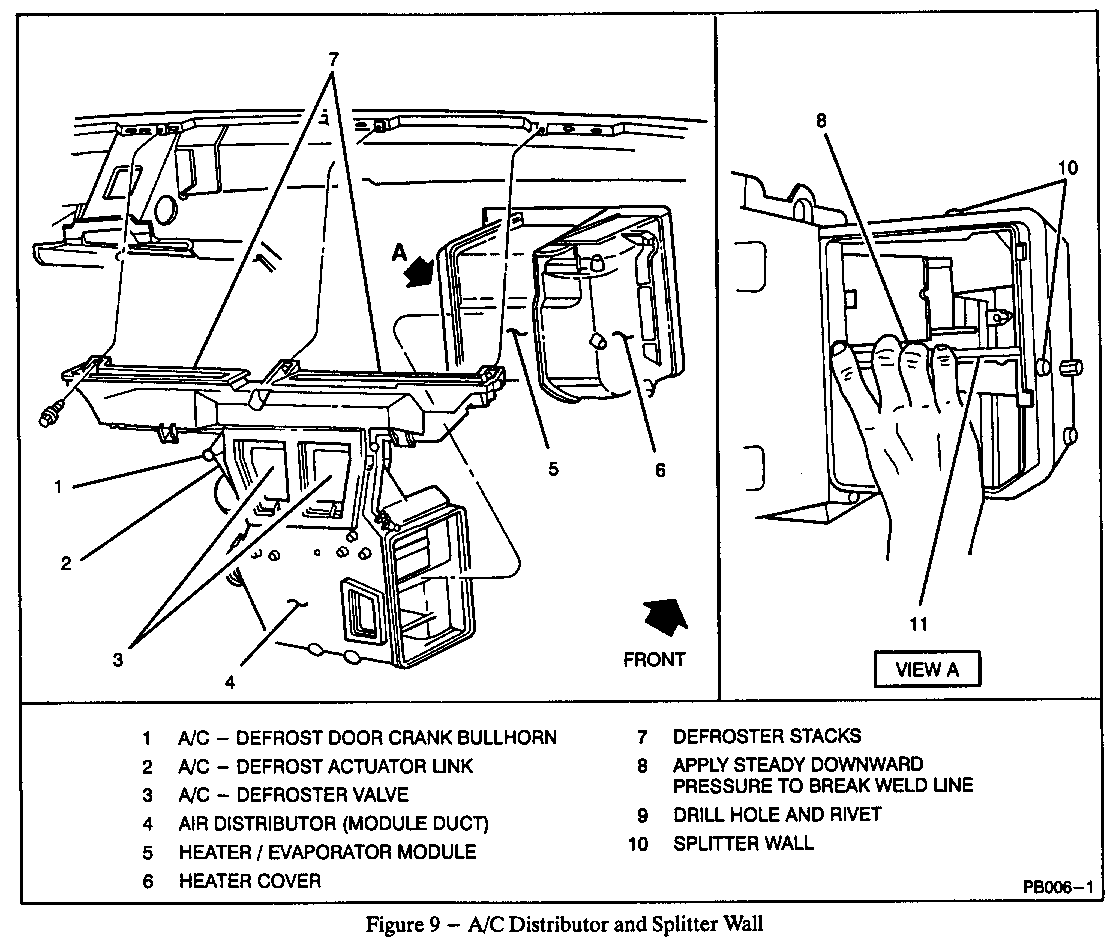
A/C Distributor (refer to Figure 9): ------------------------------------ 33. Remove three bolts from parking brake assembly.
34. Remove cross-car brace (nine bolts and four nuts).
35. Disconnect wiring harness at retainers.
36. Disconnect vacuum lines from actuators.
37. Disconnect two vacuum lines from A/C distributor.
38. Remove three screws holding A/C distributor assembly and remove assembly.
Splitter Wall With Revised Baffle (refer to Figure 9, View A):
39. Some vehicles may contain a splitter wall secured with a pop rivet. If so, drill out the existing rivet to allow for splitter wall removal.
40. Apply heat with a heat gun to welded seams holding splitter wall secure. With a slight downward pressure remove splitter wall.
41. Replace splitter wall with modified splitter, P/N 52465553.
42. Secure into place with a pop rivet.
Reassemble:
----------- 43. A/C distributor.
44. Instrument panel.
45. Steering column bracket and opening filler trim.
46. Full console assembly (if so equipped).
47. I/P upper trim panel.
48. Enable SIR system.
49. Connect battery (-) cable.
50. Perform idle learn procedure.
Parts are currently available from GMSPO.
For warranty purposes use Labor Operation T6569 at 3.2 hours for mini-console and 4.2 hours for full console.
General Motors bulletins are intended for use by professional technicians, not a "do-it-yourselfer". They are written to inform those technicians of conditions that may occur on some vehicles, or to provide information that could assist in the proper service of a vehicle. Properly trained technicians have the equipment, tools, safety instructions and know-how to do a job properly and safely. If a condition is described, do not assume that the bulletin applies to your vehicle, or that your vehicle will have that condition. See a General Motors dealer servicing your brand of General Motors vehicle for information on whether your vehicle may benefit from the information.
