BUMPER FIT - ADJUST BUMPER HEIGHT AND FASCIA

SUBJECT: BUMPER ADJUSTMENT
MODELS AFFECTED: 1992 ELDORADOS AND SEVILLES
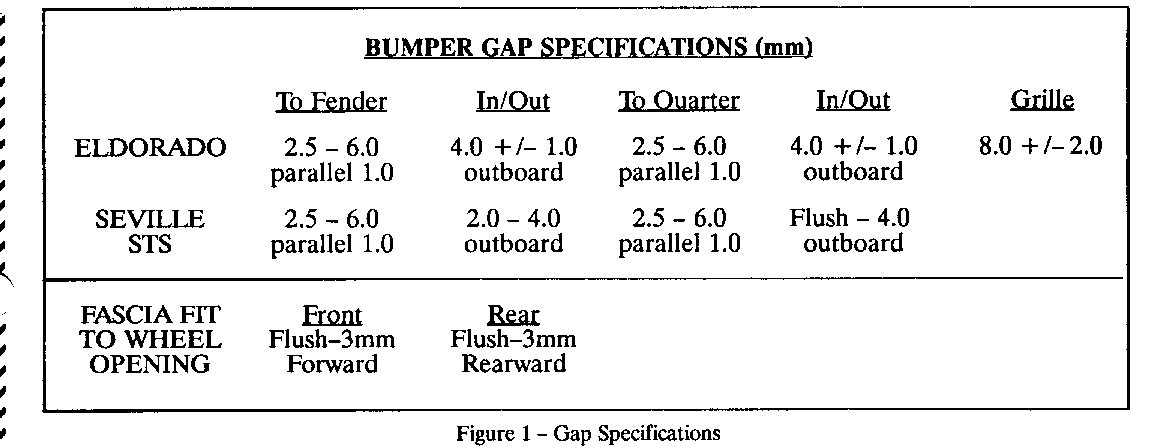
Some 1992 Eldorados and Sevilles may experience a condition where the bumper fit is objectionable due to wide or uneven gaps to the fender, quarter panel, or cross-car. The bumper fascia side wing may also be too far inboard or outboard to the sheet metal along the sides of the vehicle, or may protrude into the wheel opening. These conditions may be caused by incorrect location of the and/or surfaces. Figure 1 shows the current Engineering specifications for the bumper gap to several mating surfaces.
To correct a poor bumper fit, perform the following procedures, as required, to allow adjustment for the described conditions.
o Procedure 1 is used to adjust bumper height or to correct a condition of the bumper fascia side wing protruding into the wheel opening.
o Procedure 2 is used to raise/lower the side wing of the bumper fascia at the wheel opening and also to move the fascia outboard in relation to the fender/quarter panel.
If both adjustments are required, Procedure 1 must be completed prior to Procedure 2.
PROCEDURE 1: ADJUST BUMPER HEIGHT OR MOVE SIDE WING OUT OF WHEEL OPENING
Evaluation:
1. Ensure the bumper fillers are properly assembled to the body. Some uneven or large gap conditions result from improperly positioned fillers. Repair as necessary, then determine whether the bumper still requires adjustment. (For reference, the Labor Operations for the fillers are B0500/BO501 for the front and B1100/B1101/B11066 for the rear fillers.)
2. Measure the gap between the bumper and the body at the right and left sides to determine the amount of adjustment required.
3. If the bumper fascia side wings protrude into the wheel opening, measure to determine the shim amount required to move the bumper forward (front bumper) or rearward (rear bumper).
4. Examine the fit of the fascia side wing to the fender or quarter. If rear of side wing should be raised or lowered to provide the required fit or if shimming is required to move the fascia outboard, Procedure 2 will also have to be completed. In that case, perform the Procedure 2 Evaluation now (Steps 1-3) and make a note of the adjustments required. Procedure 1 must be completed prior to Procedure 2.
Remove/Rework:
5. Remove the screws (three each side) retaining the fascia extension (wheel opening molding) to the fascia.
6. Hoist vehicle and support the bumper using a floor stand.
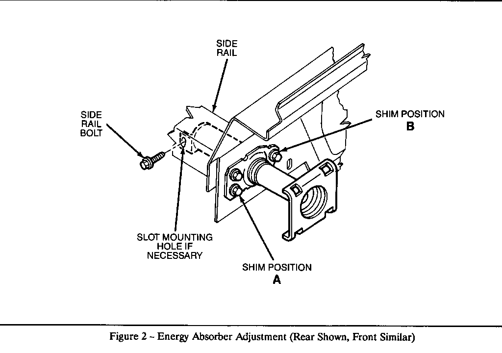
7. Remove the rear energy absorber bolt at the rail. Loosen the remaining mounting bolts/nuts.
8. Shim behind the lower bolt to tilt the absorber upward, using the table below to determine the shim amount required. For the rear bumper, the innermost bolt also requires shimming for larger adjustments. Refer to Figure 2 for location of rear bumper shim positions A and B as indicated in the table. Bumper Height Gain Shim Amount (Approximate) ----------- ------------------ FRONT: 1.0mm 1.5mm 2.0 3.0 3.0 4.5 REAR: 1.5mm at lower (A) 5.0
3.0 at lower (A), 1.5 at inner (B)9.0
NOTE: Can also apply 2.0 or 2.5mm at A with 1.0mm at B for values between 5.0 and 9.0.
9. Shim equally between the absorber and the body to move the bumper further forward (front bumper) or rearward (rear bumper), if required.
10. Tighten bolts/nuts to snug position.
11. Examine the alignment of the energy absorber L-bracket to the rail slot (for the rear energy absorber fastener). If the holes do not align, mark the position of the L-bracket on the rail to locate area to be enlarged.
NOTE: If holes do not align or if Procedure 2 is also required continue on with Steps 12-14. If holes align, go to Step 16.
12. Remove energy absorber nuts/bolts at body. Disconnect lamps. Remove splash shield fasteners (front).
13. Remove bumper along with energy absorbers.
14. Enlarge slot in rail as necessary. Apply anti-corrosion materials to the reworked area.
NOTE: If side wing adjustment is required, go to Procedure 2, Step 5.
Assemble:
15. Reassemble bumper with energy absorbers, being sure to properly center the bumper to the vehicle.
16. Torque the energy absorber fasteners to 21-31 Nm (15-23 lbs. ft.) in sequence - upper bolt/nut, inner bolt/nut, lower bolt/nut, rear bolt.
PROCEDURE 2: ADJUST SIDE WINGS OF FASCIA IN/OUT TO FENDER OR QUARTER
If the bumper fascia side wing is not parallel to the fender or quarter (uneven gap) or is too far outboard/inboard to the body panel, the following procedure can be used to adjust the side wing. If the gap is parallel but is too large or a cross-car uneven gap requires repair, Procedure 1 must be performed first. Refer to the table in Figure 1 for bumper gap and flushness specifications.
Evaluation:
1. If in/out location of fascia side wing is in question, verify that bumper is properly centered cross-car at the face of the bumper. If necessary, loosen two bolts to energy absorbers-and adjust cross-car fit. Leave bolts loose.
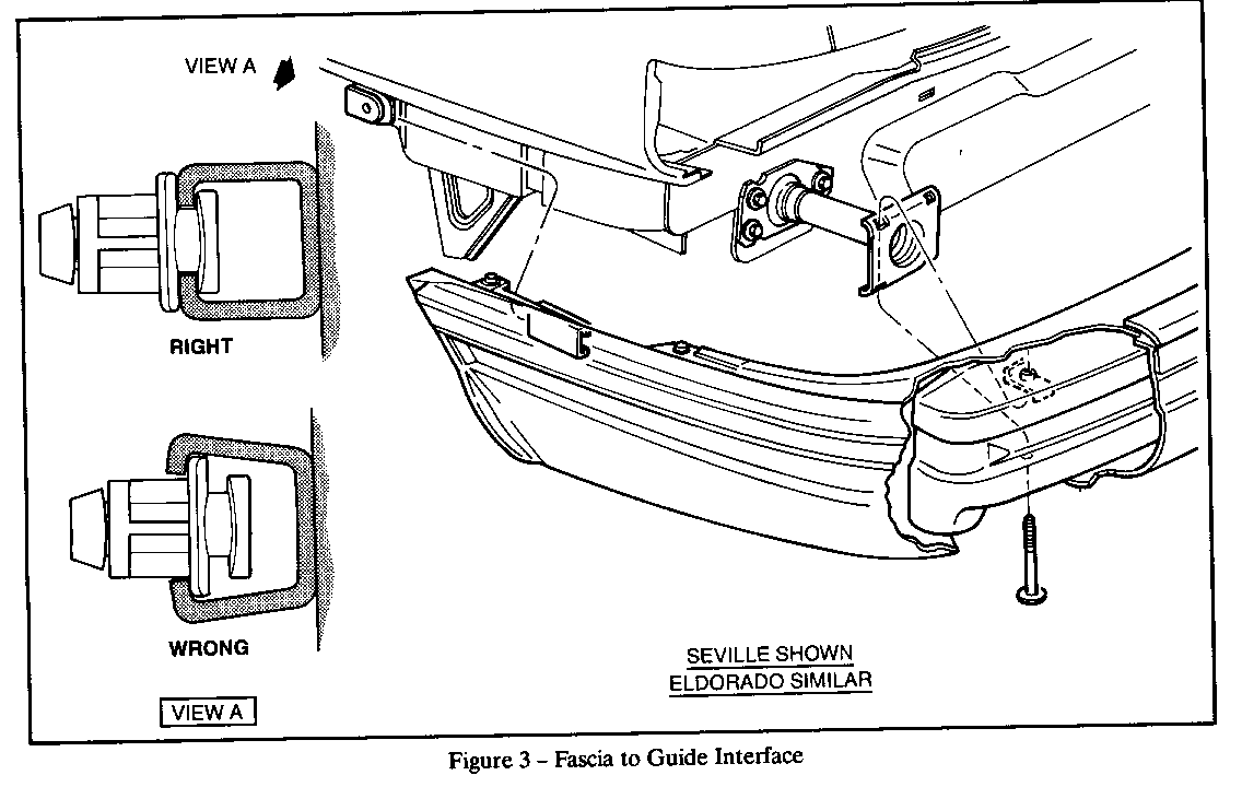
2. If in/out position still objectionable, inspect the fascia-to-guide interface to verify correct mounting of parts as shown in Figure 3. If fascia is not mounted correctly, remove bolts at energy sorbers and properly reassemble bumper to guides. Reevaluate fit before proceeding.
3. Determine whether rear of bumper fascia should be raised or lowered to provide the required fit and also if shimming is required to move the fascia outboard.
Remove/Disconnect:
4. Bumper assembly - screws at wheel opening molding, side marker lamp sockets, splash shield (front), fog lamps (if equipped), two bolts to energy absorbers. If necessary, refer to Service Information Manual Section 10-4 for additional in-formation.
5. Mark original position of fascia guide on bracket, or measure distance from bottom of fender to guide for reference when reassembling.
6. Fascia guide - release locking tab and twist to remove.
Rework:
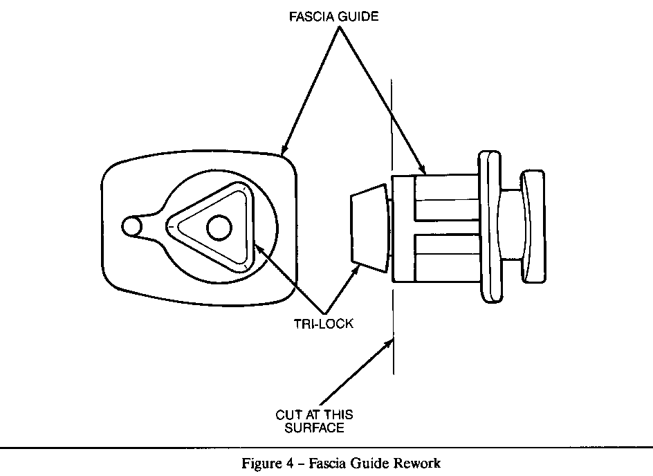
7. Using a hack saw or coping saw, cut off the tri-lock portion of the fascia guide - the triangle on the rear of the guide that fits through the body sheet metal and locks the guide to the body. Refer to Figure 4. If necessary, file or sand surface smooth. (For information, the guide part number is 3534030.)
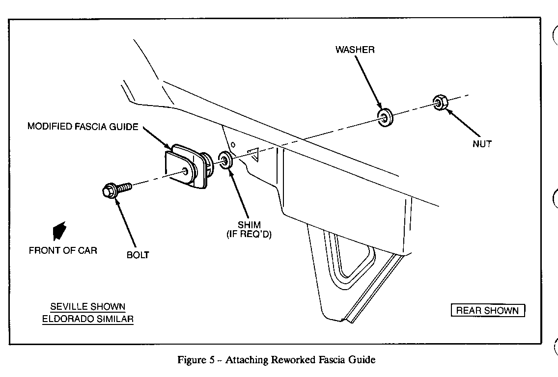
8. Loosely reassemble the modified fascia guide to the original body mounting location using the bolt, washer, and nut specified below. If necessary, additional washers can be used between the guide and sheet metal to shim the fascia outboard. Refer to Figure 5.
Bolt 14066450 Washer 10046663 Nut 11500760
Parts are currently available from GMSPO.
9. Locate the guide as desired. Positioning the bolt at the large end of the body triangle will provide approximately 7.Omm of adjustment up or down from the original guide position.
10. Using a back up wrench and keeping the guide level, torque the nut/bolt to 12-18 Nm (9-13 lbs. ft.).
Assemble:
11. Bumper assembly to vehicle - two bolts to energy absorbers, screws at wheel opening molding, side marker lamp sockets, splash shield (front), fog lamps (if equipped). If necessary, refer to Service Information Manual Section 10-4 for additional information.
If Procedure 1 was performed, torque the energy absorber fasteners to 21-31 Nm (15-23 lbs. ft.) in sequence - upper bolt/nut, inner bolt/nut, lower bolt/nut, rear bolt.

General Motors bulletins are intended for use by professional technicians, not a "do-it-yourselfer". They are written to inform those technicians of conditions that may occur on some vehicles, or to provide information that could assist in the proper service of a vehicle. Properly trained technicians have the equipment, tools, safety instructions and know-how to do a job properly and safely. If a condition is described, do not assume that the bulletin applies to your vehicle, or that your vehicle will have that condition. See a General Motors dealer servicing your brand of General Motors vehicle for information on whether your vehicle may benefit from the information.
